
Specifications
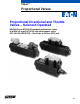
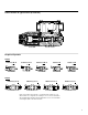
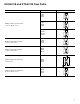
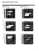
Table Of Contents

4
General Information
Typical Applications
This type of valve is often used in both
mobile and industrial “line-of-sight”
applications where speed and position are
controlled by an operator. Some examples
are aerial work platforms, entertainment
industry rides, farm combine controls,
material handling equipment, and process
controls. Any application using a
DG4V-3(S) 60-design solenoid operated
directional valve is a potential application
for the KDG4V-3(S) or KTG4V-3(S)
The standard performance KDG4V-3S or
KTG4V-3S should be used on most
applications where a tank line pressure
rating of 100 bar (1450 psi) is
acceptable. The high performance
KDG4V-3 or KTG4V-3 should be used on
applications where a tank line pressure
rating of 210 bar (3000 psi) is required.
Commonly used electrical input devices
include joystick controllers, proportional
push buttons, potentiometers, power plugs,
and amplifier cards. Input devices that
operate on the principle of direct voltage
rather than current control will require the
appropriate coil type (GP or HA).
Meter-in and Meter-out
System requirements must be clearly
understood and taken into consideration
when selecting a valve spool. Meter-out
spools have the metering notches
positioned between the actuator port and
the tank port, creating a throttle in the
hydraulic actuator’s return line. Meter-out is
the most common spool configuration and
is typically used in applications with over
center loads and/or requiring deceleration
control.
Meter-in spools have the metering notches
positioned between the pressure port and
the actuator port, creating a throttle in the
hydraulic actuator’s inlet line. Meter-in
spools are commonly used with hydrostat
modules for pressure compensation in
applications that don’t have an overrunning
load as well as in load sensing pump
circuits.
Spools with both meter-in and meter-out
flow characteristics should be specified in
applications where load changes (resistive
to overrunning or vice versa) will occur.
They should also be selected when
uncertain system dynamics prevent the
selection of specific meter-in or meter-out
spool types.
Valve Spool Position
Spring centered and spring offset valves
will be spring positioned unless the
solenoid is energized continuously.
NOTE
Due to silting, any sliding spool valve
held shifted under pressure for long
periods may stick and not spring return.
It is recommended that such valves be
cycled periodically to prevent this from
occurring.
Flow Rates
The rate of flow through a proportional
valve is dependent on spool position and
valve pressure differential. This is similar to
flow through a needle valve. Like a needle
valve, as a proportional valve is opened,
the rate of flow increases, and if the
pressure differential across the valve
changes (because of load pressure
changes, for example), the flow will vary.
Because of this phenomenon, “rated flow”
is an arbitrary term, dependent on the
above parameters.
Unlike a needle valve, however,
proportional valves exhibit an inherent
degree of load compensation whereby
increasing valve pressure drop has
progressively less effect on flow rate (see
Power Capacity Envelopes on pages 13
and 26). To eliminate the effects of
pressure changes, a hydrostat module can
be installed under the proportional valve to
achieve pressure compensation.
Recommended Fluids
Petroleum oils are recommended for use
with the KDG4V and KTG4V. Fluorocarbon
seals are standard and are suitable for use
with phosphate ester type fluids or blends,
water glycol, water-in-oil emulsion fluids,
and petroleum oils. Refer to publication
694 for fluid and temperature
recommendations. HWBF (95% water) is
not recommended.
Pressure Compensation
For information on using a SystemStak
reducing valve to achieve pressure
compensation control, please contact your
Vickers Representative.
Accessories
See page 32 for information onmounting
surface, subplate, and bolt kits.
Electrical Signals
It is important to note that solenoid force
and valve flow are proportional to
current—not voltage. Therefore, for
optimum performance, a constant current
electrical signal should be used. This type
of signal will help compensate for the drift
that would otherwise occur when current
flow causes solenoid temperature and
resistance to increase.
Flow is metered directly in proportion to the
command signal applied to the amplifier.
Metering performance is enhanced by
machined metering notches on the valve
spool. As the spool travels from its
centered position, these metering notches
create an increasingly greater orifice area,
allowing more fluid to pass.
Electrical Connectors
KDG4V-3S and KTG4V-3S
On FT (flying lead) models, electrical
connections to the valve are made in the
wiring housing, and a ground terminal is
provided. SP1 and SP2 models have
spade type terminals on each solenoid.
DIN 43650 connectors are also available
by specifying the U coil type. When U1 is
specified, DIN 443650 mating plugs are
included.
KDG4V-3 and KTG4V-3
DIN 43650 connectors are standard.
Mating plugs must be ordered separately.