
Specifications
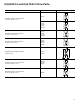
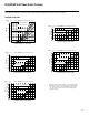
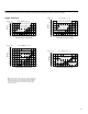
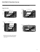
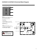
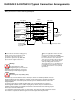
Table Of Contents
29
KADG4V-3 & KATG4V-3 Typical Connection Arrangements
Warning
Do not ground pin C. If the
local ground (pin C) is not used for
differential monitor electronics, do not use.
Read monitor pin F with respect to ground.
User panel
Outer
Screen
“KA” valve
A
B
F
G
D or E
E or D
C
+24V
0V
Demand
Signal
Solenoid
Current
Monitor
Power
Supply
Enclosure
Valve must
be connected
to ground via
subplate
0V
Input
+/– 10V
0V
Connector shell
Solenoid current monitor voltage (pin F)
will be referenced to the KA valve local
ground. A “local ground” (pin C) is
provided for optional use by differential
input customer supplied electronics.
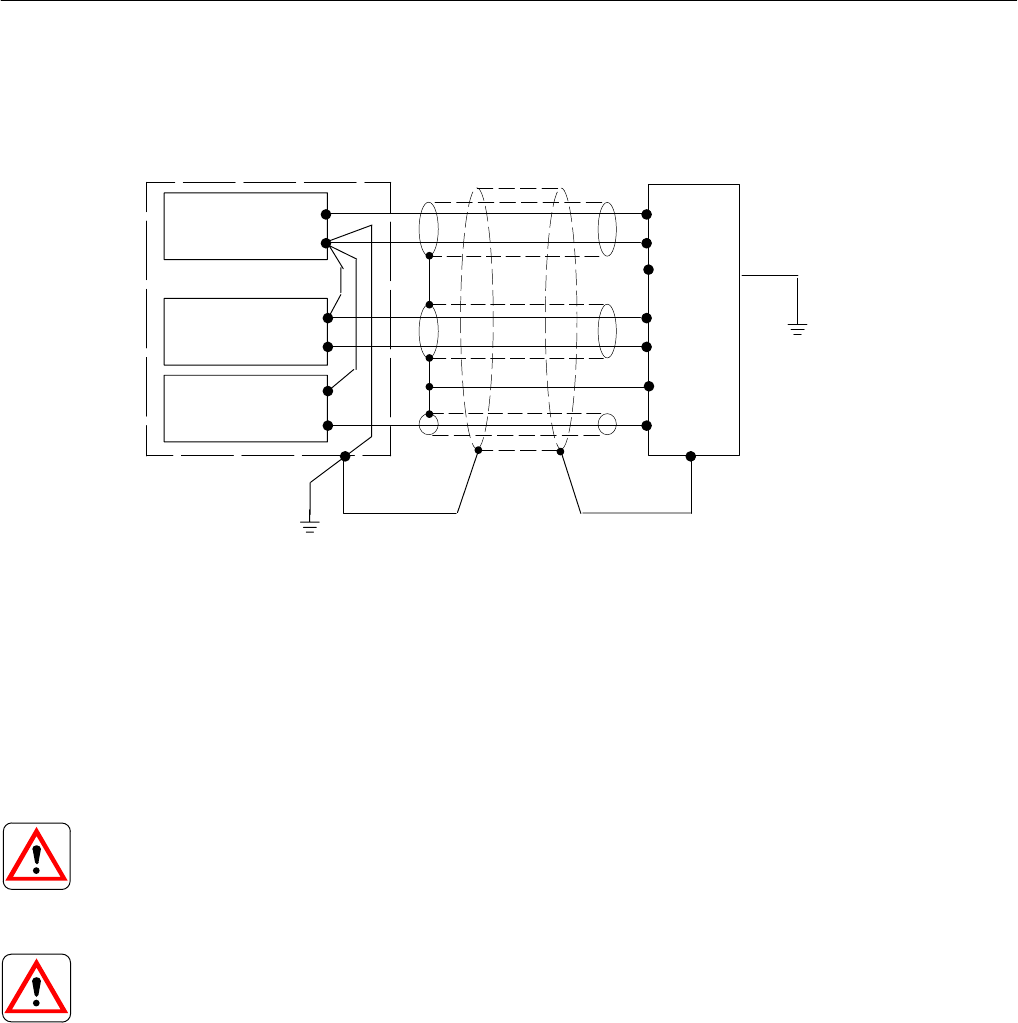
Wiring Connections for Valves with integral Amplifier
Note: In applications where the valve
must conform to European RFI/EMC
regulations, the outer screen (shield) must
be connected to the outer shell of the
7-pin connector and the valve body must
be fastened to the earth ground. Proper
earth grounding practices must be
observed in this case, as any differences
in command source and valve ground
potentials will result in a screen (shield)
ground loop.
0V must be
connected
to ground
Warning
Electromagnetic Compatibility (EMC)
It is necessary to ensure that the valve is wired-up as above. For effective protection, the user
electrical cabinet, the valve subplate or manifold, and the cable screens should be connected to
efficient ground points. The metal 7-point connector, part no. 934939, should be used for the
integral amplifier.
In all cases, both valve and cable should be kept as far as possible from any sources of
electromagnetic radiation such as cables carrying heavy current, relays and certain kinds of
portable radio transmitters, etc. Difficult environments could mean that extra screening may be
necessary to avoid the interference.
It is important to connect the 0V lines as shown above. The multi-core cable should have at least
two screens to separate the demand signal and monitor output from the power lines.
Drain wire
Inner screen