
Specifications
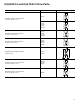
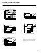
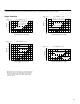
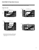
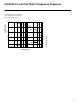
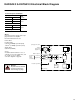
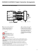
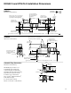
Table Of Contents
Wiring
Connections must be made via the 7-pin
plug mounted on the amplifier.
Recommended cable sizes are:
Power cables:
For 24V supply
0,75 mm
2
(18 AWG) up to 20m (65 ft)
1,00 mm
2
(17 AWG) up to 40m (130 ft)
Signal cables:
0,50 mm
2
(20 AWG)
Screen:
A suitable cable would have 7 cores, a
separate screen for the signal wires, and
an overall screen. See wiring
connection diagram on page 29.
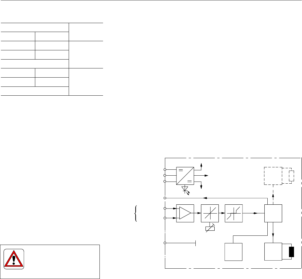
Gain
Modulator
+15V
Valve envelope
7-pin plug connections
+24V
A
Power 0V
Signal 0V
Protective ground
Solenoid drive 2
Deadband
Positive
Monitor output
Negative
Command
signal
voltage
(see table)
–15V
0V
Solenoid drive 1
B
C
F
D
E
G
Dither
28
KADG4V-3 & KATG4V-3 Electrical Block Diagram
Command Signals and Outputs
7-pin plug
Flow
Pin D Pin E
Flow
direction
Positive 0V
0V Negative
P to A
U
D
-U
E
= Positive
Negative 0V
0V Positive
P to A
U
D
-U
E
= Negative
Warning
All power must be switched
off before connecting or
disconnecting any plugs.