
Specifications
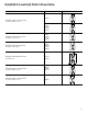
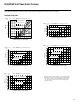
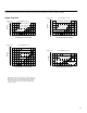
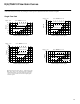
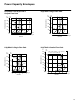
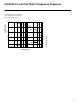
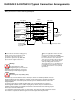
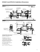
Table Of Contents
23
7
6
5
4
3
2
1
25
20
15
10
5
Single Flow Path
At the stated valve pressure drops, the percentage command signals are applicable to whichever solenoid is energized.
Curves shown are for spool types 2". These points will vary
from valve to valve, but can be adjusted using the deadbandĆ
compensation feature of the drive amplifier. For spool types
33", the curves are similar, but flow starts at slightly higher
command signals.
Command signal (% of max. signal)
Flow rate
30 bar (435 psi)
100 bar (1450 psi)
350 bar
(5080 psi)
5 bar (72 psi)
0 !02030405060708090100
Spool 2C20N" P to A or B
l/min
USgpm
16
14
12
10
8
6
4
2
17,5
15,0
12,5
10,0
7,5
5,0
2,5
5.0
4.0
3.0
2.0
1.0
12
10
8
6
4
2
100 203040 50 6070 80 90100
Command signal (% of max. signal)
100 203040 506070 80 90100
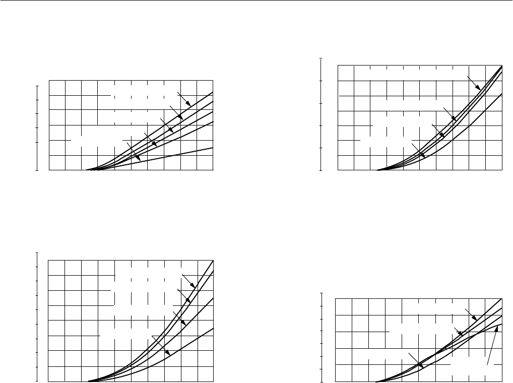
Command signal (% of max. signal)
l/min
USgpm
USgpm
4.5
4.0
3.5
3.0
2.5
2.0
1.5
1.0
0.5
3.0
2.5
2.0
1.5
1.0
0.5
l/min
USgpm
Flow rateFlow rate
100 203040 506070 80 90100
Command signal (% of max. signal)
Flow rate
l/min
Spool 2C03F" P to A or B
Spool 2C07N" P to A or B
Spool 2C13N" P to A or B
100Ć350 bar (1450Ć5080 psi)
50 bar (725 psi)
30 bar (435 psi)
5 bar (72 psi)
350 bar (5080 psi)
100 bar (1450 psi)
30 bar (435 psi)
5 bar (72 psi)
350 bar (5080 psi)
100 bar (1450 psi)
50 bar (725 psi)
30 bar (435 psi)
5 bar (72 psi)