
Specifications
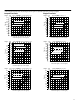
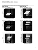
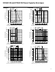
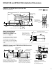
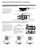
Table Of Contents

20
KADG4V-3 and KATG4V-3 Application Data
KAD/TG4V-3 Valves with Integral Amplifiers
Power supply
24V DC (21V to 36V including 10% peak-to-peak max. ripple)
max. current 3A
Command signal
Input impedance
0 to +10V DC, or 0 to –10V DC, or –10V to +10V DC
47 kΩ
7-pin plug connector
Pin connections:
A
B
C
D
E
F
G
Power supply +ve
Power 0V
Signal 0V
+ve voltage command signal
–ve voltage command signal
Monitor output
Protective ground
Electro-magnetic compatibility (EMC):
Emission (10 v/m)
Immunity (10 v/m)
See notes regarding EMC, below and on pages 18 and 29.
EN 50081-2
EN 50082-2
Gain adjustment 25 to 125%
Factory set adjustments Deadband, gain, dither and offset
Monitor point signal
Output impedance
0,5V per amp solenoid current
10 kΩ
Power stage PWM frequency 2 kHz nominal
Repeatability, valve-to-valve (at factory settings):
Flow gain at 100% command signal
v5%
Protection:
Electrical
Mechanical
Reverse polarity protected
IEC 144, Class IP65
Relative humidity 65 to 85% at 20 to 70C (68 to 158F)
Supporting products:
Auxiliary electronic modules (DIN-rail mounting):
EHA-CON-201-A-2* signal converter
EHD-DSG-201-A-1* command signal generator
EHA-RMP-201-A-2* ramp generator
EHA-PID-201-A-2* PID controller
Subplates, size 03
Mounting bolts
Note: If not using Vickers recommended bolt kits, bolts must be to ISO 898 grade 12.9 or stronger.
This product has been designed and tested to meet specific standards outlined in the European
Electromagnetic Compatibility Directive (EMC) 89/336/EEC, amended by 91/263/EEC, 92/31/EEC and
93/68/EEC, article 5. For instructions on installation requirements to achieve effective protection levels,
see this leaflet, the Installation Wiring Practices for Vickers Electronic Products leaflet 2468, and leaflet
02-123931A which is packed with every KA valve. Wiring practices relevant to this Directive are indicated by
Electromagnetic Compatibility (EMC).