
Specifications
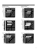
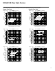
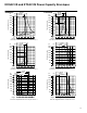
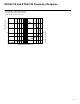
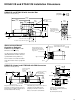
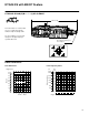
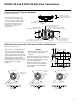
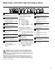
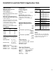
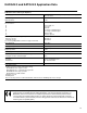
Table Of Contents

19
K(A)DG4V-3 and K(A)TG4V-3 Application Data
Operating temp 20 to 82C. . .
(–4 to 180F)
Fluid viscosity 16 – 54 cSt. . .
(75–250 SUS)
Weights (approximate)
KDG4V–3–*–60 2,4 kg (5.30 lbs.). . .
KTG4V–3–*–60 1,7 kg (3.75 lbs.). . .
KADG4V–3–*–60 2,8 kg (6.20 lbs.). .
KATG4V–3–*–60 2,1 kg (4.65 lbs.). .
Required Time to reach 90% . . . . . .
step: of req’d step:. . . . . . . . .
0 to 100% 25 ms. . . . .
100% to 0 30 ms. . . . .
+90 to –90% 35 ms. . .
Step Input Response
Drain
On 2-way valves, “T” is the drain and
must be connected to the tank through
a surge-free line, so there will be no
back pressure at this port.
Solenoid Specifications
Maximum current @ 50C (122 F)
ambient
G 3.5A
H 1.6A
GP 3.0A
HA 0.94A
Coil Resistance @ 20C (68 F)
G 1.55 Ohms
H 7.3 Ohms
GP 2.0 Ohms
HA 22.1 Ohms
Coil Inductance @ 1000 Hz
G4 mH
H 20 mH
GP 6 mH
HA 55 mH
Relative duty factor
Continuous rating ED = 100%
Type of protection, with electrical
plugs fitted correctly
IEC 144 Class IP65
Maximum operating pressure
(A, B and P ports)
350 bar (5000 psi)
(See “Flow Gain Curves”)
Maximum tank line pressure (T port)
210 bar (3000 psi)
Maximum recommended pressure
drop (four–way models at max. flow)
210 bar (3000 psi)*
*At pressure drops above 10 bar (145
psid) dither amplitudes in the electronic
controller may need to be set at or
near minimum to eliminate potential
high frequency circuit noise.
Specifications
Frequency Response
See graph on page 14.
Performance
Hysteresis
At p = 5 bar (72 psi) t8% at. . . . . .
rated flow
Reproducibility, valve-to-valve
Optimized by adjustment of deadband
compensation, gain and ramp
potentiometers on associated Vickers
amplifier.
EEA–PAM–523–A–30
EEA–PAM–523–B–30
EEA–PAM–523–C–30
EEA–PAM–523–D–30
EEA–PAM–523–E–30
EEA–PAM–523–F–30
Amplifiers
Plug Amplifier
EHH–AMP–702–C–10
EHH–AMP–702–D–10
EHH–AMP–702–E–10
EHH–AMP–702–F–10
Amplifier
Coil Voltage
Identification
Letter
GP
HA
H
G EHH–AMP–712–D/G–20
Refer to drawing I-521575 for information.
EM–VT–12–10
EM–VP–12–10
EM–VT–24–10
EM–VP–24–10
H
l/min
Spool
Code
in
3
/min
coef
**C03F
**C07F
**C13F
**C20F
**C28S
0,2
0,4
0,6
1,0
1,4
12
24
36
60
85
Minimum recommended flow rates
for K(A)DG4V-3
Mounting pattern
ISO–4401–AB–03–4–A, NFPA D03,
CETOP 3
At p = 5 bar (72 psi) per metering path.