
Specifications
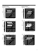
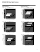
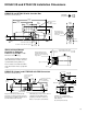
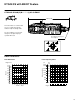
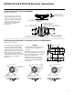
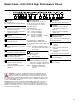
Table Of Contents
18
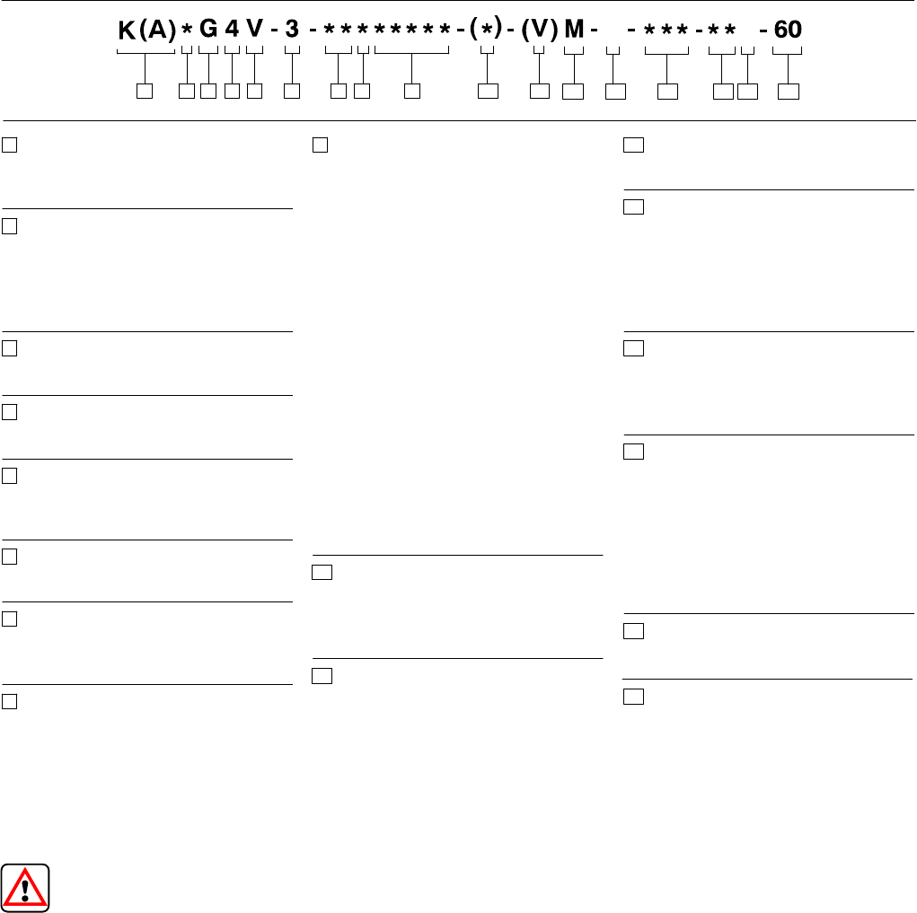
Model Code – K(A)*G4V-3 High Performance Valves
Warning: To conform to the EC Electromagnetic Compatibility directive
(EMC), this KADG4V or KATG4V valve must be fitted with a metal 7-pin
plug. The screen of the cable must be securely connected to the shell of
the metal connector. A suitable IP67 rated connector is available from Vickers, part
no. 934939. Alternatively, a non IP67 rated connector is available from ITT-Cannon,
part no. CA 02 COM-E 14S A7 P.
Additionally, the cable must be fitted with a ferrite EMC suppression core not more
than 4cm from the connector referred to above. Suitable types include Farnell
535-898 or Farnell 535-904 which snap-fit over the cable. The plastic plug, part no.
694534, is only suitable for use in a sealed electromagnetic environment or outside
of the European Community
Spool flow rating
For looped flow path P→A→B→T or
P→B→A→T: ∆p= 10 bar (145 psi).
For single flow path P→A or B→T:
∆p= 5 bar (72 psi).
Symmetric Spools
03F – 3 l/min (0.8 USgpm)
07N – 7 l/min (1.8 USgpm)
13N – 13 l/min (3.4 USgpm)
20N – 20 l/min (5.3 USgpm)
28S – 28 l/min (7.4 USgpm) – available
with type 2 spool only
Asymmetric Spool – KDG4V Only
First figure (20N) is flow rating P→A or
A→T; last figure (N10) is flow rating P→B
or B→T.
20N10 – 20 l/min (5.3 USgpm) “A” port
flow, and 10 l/min (2.65 USgpm)
“B” port flow
Manual override(s)
H – Water-resistant
Z – No override(s)
Blank – Plain override(s)
Solenoid energization identity
V – Solenoid identification determined
by position of solenoid (solenoid A on
A port end, solenoid B on B port end)
Blank – Standard per ANSI B93.9
(energize solenoid A, flow
is (P→A)
Flag symbol
M – Electrical options and features
Coil type
U – DIN 43650 connector. Order
solenoid plug separately; see
page 30.
F – Flying lead solenoids (KA type
valves only)
Electrical connection
(KA valves only)
PD7 – 7-pin connector with plastic plug.
See warning note below.
Coil voltage rating
G – 12V DC
H – 24V DC
GP – Direct 12V DC or EM-VP/VT
amplifier
HA – Direct 24V DC or EM-VP/VT
amplifier
KA type valves must have H type coils.
Tank pressure rating
7 – 210 bar (3000 psi)
Design number
Subject to change.
17
Valve type
K – Proportional
KA– Proportional with integral amplifier
Valve function
D – Directional valve (Double solenoid,
C models. See item 8.)
T – Throttle valve (Single solenoid, B
models. See item 8.)
Mounting
G – Subplate/manifold mounted
Operation
4 – Solenoid operated
Pressure rating
V – 350 bar (5075 psi) on P, A, and B
ports
Interface
3 – ISO 4401-03, CETOP 3 (NFPA D03)
Spool type (center condition)
2 – Closed center (all ports)
33 – P port closed, bleed A and B to T
Spool/spring arrangement
B – Spring centered, solenoid A
removed – KTG4V-3
C – Spring centered, dual solenoid –
KDG4V-3
3 4 5 6 9 101 2 11
12 13 14 15 16
3
4
5
6
7
8
9
10
13
14
15
1
2
16
7 8
U
11
7
17
12