
Specifications
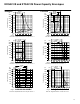
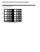
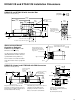
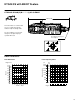
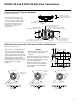
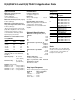
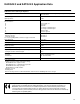
Table Of Contents
15
KDG4V-3S and KTG4V-3S Installation Dimensions
25,75
(1.014)
KDG4V-3S and KTG4V-3S with Junction Box
Dimensions in mm (inches)
3rd angle
projection
Two lead wires per
solenoid with M3 size
terminals for customer
connections
23,00
(0.906)
26,25
(1.033)
“F” and “B” models only
“F” and “B” models with “P2” options
24.60
(0.96)
3,0
(0.12)
66,75
(2.828)
130,07
(5.121)
219,63
(8.647)
Thread connection
“W” – NPT
“J” – M20 × 1.5-8H
68,65
(2.703)
91,15
(3.589)
21,75
(0.86)
44,65
(1.758)
46,00
(1.811)
49,25
(1.939)
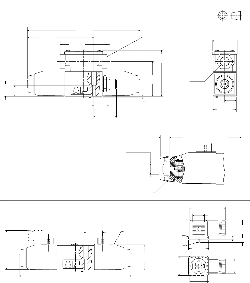
KDG4V-3S (shown) and KTG4V-3S with DIN Connectors
Dimensions in mm (inches).
Plug connector can be positioned in 90°
increments on valve by removing connector
housing and re-assembling contact holder at
desired orientation inside housing.
Seal
51 (2.01)
27
(1.06)
22,5
(0.88)
∅
M3 thread
5,5
(0.22)
1,5
(0.06)
30,5
(1.20)
26,5 (1.04)
27,5
(1.08)
18
(0.71)
Coil types: U (shown),
SP1, and SP2
(see Model Code)
219,63 (8.647)
78.90
(3.10)
51,90
(2.044)
33,00
(1.299)
Conductor cross-sectional area:
0,5 to 1,5 mm
2
(0.0008 to 0.0023 in
2
)
Cable diameter:
6 to10 mm (0.24 to 0.40 in)
Water-resistant Manual
Override on Solenoid
K*G4V-3S-**(L)-H-(V)M-**-**-60
Dimensions in mm (inches)
Use where finger operation is required.
(Standard manual overrides cannot be
operated without using small tool.)
This “H” feature is not field-convertible
from other models. Please specify with
order.
Spacer
15
(0.6)
Overall length of valve with
standard manual overrides
Manual actuation must be
applied within this diameter.
Spacer prevents actuation by
larger device.
Approx. ∅ 20 (0.75)
DIN 43650 plug connector can be ordered
separately or included with valve by
specifying 1 for Model Code item 19.
Means of connection: screw terminals
Center of mounting
hole to center
of female
connector