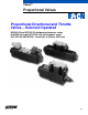
Vickers® Proportional Valves Proportional Directional and Throttle Valves – Solenoid Operated KDG4V-3S and KTG4V-3S standard performance series K(A)DG4V-3 and K(A)TG4V-3 high performance series ISO 4401-03 (NFPA D03) – Pressures to 350 bar (5075 psi) Revised 11/98 539
Introduction KDG and KTG Valves Vickers KDG and KTG valves are non-feedback type proportional valves. The KDG is a proportional directional valve with two solenoids (C models). It incorporates control of flow, direction, acceleration, and deceleration in a single control valve. The KTG is a proportional throttle valve with a single solenoid. B models are spring centered with solenoid A removed. F models are spring offset to port A and respond to an increasing signal by reducing the flow rate.
Contents General Information Typical Applications, Meter-in and Meter-out, Valve Spool Position, Flow Rates, Recommended Fluids, Pressure Compensation, Accessories, Electrical Signals, Electrical Connectors . . . . . . . . . . . . . . . . . . . . . . . . . . . . . . . . . 4 Cross Section of Typical Valve, Graphical Symbols . . . . . . . . . . . . . . . . . . . . . . . . . . . . . . . . . . . . . . . . . . . . . . . . . . . . . . . . . . 5 System Calculations for Valve Selection . . . . . . . . . . . . . .
General Information Typical Applications This type of valve is often used in both mobile and industrial “line-of-sight” applications where speed and position are controlled by an operator. Some examples are aerial work platforms, entertainment industry rides, farm combine controls, material handling equipment, and process controls.
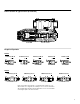
Cross Section of Typical Valve (KTG4V-3S) Solenoid B Port A Port B Graphical Symbols KTG4V KTG4V-3S-2B**N KTG4V-3S-2F**N A B b A B b KTG4V-3-2B KTG4V-3S-33B**A A B b KTG4V-3-33B A B A B P T P T P T P T P T KDG4V KDG4V-3(S)-2C**N b A B P T KDG4V-3(S)-2C**S a b A B P T KDG4V-3S-33C**A a b A B KDG4V-3-33C**N a b A B P T P T a Note: On all models, when solenoid a" is energized, flow is always P" to A". When solenoid b" is energized, flow is always P" to B".
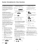
System Calculations for Valve Selection The “rated flow” values for this range of proportional valves are determined with a looped flow path pressure drop (e.g. P→A→B→T) of 10 bar (145 psi) when the valve is fully open. As explained on page 4, however, “rated flow” is an arbitrary term dependent upon external factors. It is important to properly size a proportional valve to achieve good resolution. A common mistake in specifying proportional valves is selecting too high a rated flow.
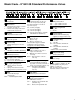
Model Code – K*G4V-3S Standard Performance Valves 1 1 2 3 4 5 6 7 8 9 10 Valve type K – Proportional 2 Valve function D – Directional valve (Double solenoid, C models. See item 9.) T – Throttle valve (Single solenoid, B and F models. See item 9.) 3 Mounting 11 12 11 13 14 15 16 17 Spool flow rating For looped flow path P→A→B→T or P→B→A→T: ∆p=10 bar (145 psid). For single flow path P→A or B→T: ∆p= 5 bar (72 psi).
KDG4V-3S and KTG4V-3S Application Data Specifications Solenoid Specifications Maximum operating pressure (A, B and P ports) 350 bar (5000 psi) (See “Flow Gain Curves”) Maximum current @ 50 C (122 F) ambient G 3.2A H 1.6A Maximum tank line pressure (T port) K*G4V-3S:100 bar (1450 psi) Maximum recommended pressure drop (four–way models at max.
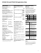
KDG4V-3S and KTG4V-3S Flow Paths Valve/Flow Path Spool 2C08S 2C15S 2C19S KDG4V-3S with Looped Flow Path. P→A or B, plus B or A→T 2C08N 2C15N 2C19N 33C08A 33C15A 33C22A KDG4V-3S with Single Flow Path. P→A or B, or A or B→T KTG4V-3S with Single Flow Path. P→A or B, or A or B→T KTG4V-3S with Parallel Flow Path. P→B and A→T KTG4V-3S with Looped Flow Path.
KDG4V-3S Flow Gain Curves At the stated valve pressure drops, the percentage command signals are applicable to whichever solenoid is energized. Looped Flow Path USgpm l/min Flow rate 4.0 3.5 3.0 Looped Flow Path USgpm l/min 20 10.0 18 9.0 16 7.0 12 2.5 10 2.0 8 1.5 6 1.0 4 .5 0 2 8.0 100 bar (1450 psi) 14 30 bar (435 psi) 10 bar (145 psi) Flow rate 5.0 4.5 Spool 2C08S" P-A or B plus B or A-T 6.0 5.0 Flow rate 8.0 7.0 6.0 12 1.0 8 0 4 5.0 4.0 2.0 8 1.0 4 10.0 9.
At the stated valve pressure drops, the percentage command signals are applicable to whichever solenoid is energized. USgpm l/min 20 5.0 18 4.5 16 4.0 14 3.5 12 3.0 10 2.5 8 2.0 Spool 33C08A" P-A or B plus B or A-T Flow rate 100 bar (1450 psi) 1.5 6 1.0 4 .5 2 30 bar (435 psi) 10 bar (145 psi) Single Flow Path USgpm l/min 20 5.0 18 4.5 16 4.0 14 3.5 12 3.0 10 2.5 8 2.0 Flow rate Looped Flow Path 1.5 6 1.0 4 .
KDG4V-3S Flow Gain Curves At the stated valve pressure drops, the percentage command signals are applicable to whichever solenoid is energized. Single Flow Path 3.0 12 2.0 8 1.0 4 0 9.0 8.0 Flow rate 7.0 6.0 5.0 4.0 9.0 8.0 7.0 50 bar (725 psi) 30 bar (435 psi) 5 bar (72.5 psi) l/min 40 Spool 2B15N" P-B or A-T 36 32 28 24 20 16 3.0 12 2.0 8 1.0 4 50 bar (725 psi) 30 bar (435 psi) 4.0 16 3.0 12 2.0 8 1.0 0 4 Spool 2B19N" P-B or A-T 50 bar (725 psi) 30 bar (435 psi) 5 bar (72.
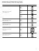
KDG4V-3S and KTG4V-3S Power Capacity Envelopes KDG4VĆ3S Valve pressure drop 3000 2800 2400 2000 1800 1200 800 400 bar 210 200 33C22A" 33C08A" 33C15A" KTG4VĆ3S psi 3000 2800 180 160 Valve pressure drop psi 140 120 100 80 60 40 210 200 2400 160 2000 1800 1200 800 400 2C19N" 2C15N" 2C08N" 180 Valve pressure drop Valve pressure drop 3000 2800 1800 140 120 100 80 60 40 2400 2000 1800 1200 800 400 120 100 800 60 40 20 psi bar 3000 2800 210 200 2400 160 2000 1800 2C08S" 2C19
KDG4V-3S and KTG4V-3S Frequency Response For amplitude of "25% maximum stroke (center to offset) about 50% position and p (P→A→B→T)=10 bar (145 psi).
KDG4V-3S and KTG4V-3S Installation Dimensions KDG4V-3S and KTG4V-3S with Junction Box 3rd angle projection Dimensions in mm (inches) 219,63 (8.647) 130,07 (5.121) 26,25 (1.033) 66,75 (2.828) Thread connection “W” – NPT “J” – M20 × 1.5-8H 49,25 (1.939) 91,15 (3.589) Two lead wires per solenoid with M3 size terminals for customer connections 68,65 (2.703) 24.60 (0.96) 21,75 (0.86) “F” and “B” models only 25,75 (1.
KTG4V-3S with EN427 Feature KTG4V-3S-2B 08N-(V)M-*** *** *(1)-H5-60-EN427 189,27 (7.45) This valve feature is recommended for use as a pilot valve with the Valvistor Slip-in Cartridge Valve. The spool adjuster is preset at the factory. Do not adjust. Improper operation will result. Spool adjuster (Factory set. Do not adjust) P B A T EN427 Performance Flow Gain Curve Power Capacity Curve psi USgpm l/min. 4.0 Flow rate 3.5 3.0 70 bar (1015 psi) 20 18 16 14 2.5 12 2.0 10 1.5 8 1.0 6 .
KDG4V-3S and KTG4V-3S Electrical Connections Terminal Strip for FT (Flying Lead) Models Dimensions in mm (inches) Conduit box cover and nameplate complete with sealing gasket and 4 screws * Difference in dimensions helps ensure correct orientation of nameplate to valve. ** For DC coils, positive + lead(s) must be connected to terminal(s) marked +. When using 3-wire incoming leads to double solenoid valves (i.e. common neutral), inner pair of terminals must be interconnected.
Model Code – K(A)*G4V-3 High Performance Valves 7 U 1 1 2 3 4 5 6 Valve type K – Proportional KA– Proportional with integral amplifier 2 Valve function D – Directional valve (Double solenoid, C models. See item 8.) T – Throttle valve (Single solenoid, B models. See item 8.) 3 Mounting G – Subplate/manifold mounted 7 8 9 10 11 12 9 Spool flow rating For looped flow path P→A→B→T or P→B→A→T: ∆p= 10 bar (145 psi). For single flow path P→A or B→T: ∆p= 5 bar (72 psi).
K(A)DG4V-3 and K(A)TG4V-3 Application Data Specifications Performance Amplifiers Maximum operating pressure (A, B and P ports) 350 bar (5000 psi) (See “Flow Gain Curves”) Frequency Response See graph on page 14. Hysteresis At p = 5 bar (72 psi) . . . . . . t8% at rated flow Coil Voltage Identification Amplifier Letter Reproducibility, valve-to-valve Optimized by adjustment of deadband compensation, gain and ramp potentiometers on associated Vickers amplifier.
KADG4V-3 and KATG4V-3 Application Data KAD/TG4V-3 Valves with Integral Amplifiers Power supply 24V DC (21V to 36V including 10% peak-to-peak max. ripple) max.
K(A)DG4V-3 and K(A)TG4V-3 Flow Paths Valve/Flow Path Spool Symbol A B P T A B P T A B P T A B P T A B P T A B P T **C28S K(A)DG4V-3 with Looped Flow Path. P→A or B, plus B or A→T **C03F **C07N **C13N **C20N K(A)DG4V-3 with Single Flow Path. P→A or B, or A or B→T K(A)TG4V-3 with Single Flow Path. P→A or B, or A or B→T K(A)TG4V-3 with Parallel Flow Path. P→B and A→T K(A)TG4V-3 with Looped Flow Path. P→A or B, plus B or A→T K(A)TG4V-3 with Looped Flow Path.
K(A)DG4V-3 Flow Gain Curves At the stated valve pressure drops, the percentage command signals are applicable to whichever solenoid is energized. Looped Flow Path 2.5 Flow rate 2.0 1.5 l/min 9 Spool 2C03F" P to A or B plus B or A to T 350 bar (5080 psi) 8 100 bar (1450 psi) 7 6 6 50 bar (725 psi) 30 bar (435 psi) 5 1.0 USgpm 4 Flow rate USgpm 10 bar (145 psi) 3 0.
At the stated valve pressure drops, the percentage command signals are applicable to whichever solenoid is energized. Single Flow Path 2.0 8 1.5 6 1.0 4 0.5 Spool 2C03F" P to A or B 350 bar (5080 psi) 100 bar (1450 psi) 50 bar (725 psi) 30 bar (435 psi) 5 bar (72 psi) 2 3.0 2.0 1.0 0 10 20 100Ć350 bar (1450Ć5080 psi) 4.0 15,0 Flow rate Flow rate USgpm l/min 12 3.0 10 2.5 Spool 2C13N" P to A or B USgpm l/min 5.
K(A)TG4V-3 Flow Gain Curves At the stated valve pressure drops, the percentage command signals are applicable to whichever solenoid is energized. Single Flow Path 2.0 8 1.5 6 1.0 4 0.5 2 Spool 2B03F" P to A or B 350 bar (5080 psi) 100 bar (1450 psi) 50 bar (725 psi) 30 bar (435 psi) 5 bar (72 psi) 3 2 1 0 10 100Ć350 bar (1450Ć5080 psi) 4 15,0 Flow rate Flow rate USgpm l/min 12 3.0 10 2.
At the stated valve pressure drops, the percentage command signals are applicable to whichever solenoid is energized. Parallel Flow Path USgpm l/min 8 30 7 6 Flow rate 5 Spool 2B13N" P to B and A to T 100 bar (1450 psi) 25 30 bar (435 psi) 20 210 bar (3000 psi) 4 15 3 10 2 5 1 5 bar (72 psi) 0 10 20 30 40 50 60 70 80 90 100 Command signal (% of max.
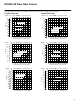
Power Capacity Envelopes K(A)DG4VĆ3 and K(A)TG4VĆ3 Looped Flow Path 4000 3000 psi 5000 bar 350 28S 300 03F 200 2000 1000 0 20N 07N 100 10 0 2 20 4 4000 3000 200 B07N 6 30 40 l/min 8 10 USgpm 100 0 0 350 3000 3500 3000 300 C07N 200 C20N C13N 2000 100 C03F 1000 0 0 10 2 20 4 Flow rate 30 l/min 6 2 4 30 l/min 6 8 USgpm 8 USgpm bar 250 Max. system pressure = max.
K(A)DG4V-3 and K(A)TG4V-3 Frequency Response For amplitude of "25% maximum stroke about the 50% position, at p (P→B) = 5 bar (72 psi).
KADG4V-3 & KATG4V-3 Electrical Block Diagram Command Signals and Outputs 7-pin plug Pin D Pin E Positive 0V 0V Negative Flow direction P to A UD-UE= Positive Negative 0V 0V Positive P to A UD-UE= Negative Wiring Connections must be made via the 7-pin plug mounted on the amplifier.
KADG4V-3 & KATG4V-3 Typical Connection Arrangements Wiring Connections for Valves with integral Amplifier User panel Power Supply Outer Screen “KA” valve +24V A B 0V C Inner screen Demand Signal 0V +/– 10V Solenoid Current Monitor 0V Input D or E E or D Drain wire G Valve must be connected to ground via subplate F Enclosure 0V must be connected to ground Solenoid current monitor voltage (pin F) will be referenced to the KA valve local ground.
KDG4V-3 and KTG4V-3 Installation Dimensions KDG4V-3 3rd angle projection Dimensions in mm (inches) ∅ 5,6 (0.22) thru. ∅ 9,0 (0.35) c’bore to depth shown. 4 places Plug connector can be repositioned in 90° increments by loosening knurled nut, turning coil, and re-tightening. 14,0 (0.55) for weather-resistant manual overrides 74,0 (2.9) 13,0 (0.5) for plug removal 14,0 (0.55) for weather-resistant manual overrides 35,0 (1.4) 51,0 (2.0) 24,5 (0.96) 21,75 (0.86) 16,8 (0.66) 10,0 (0.
KADG4V-3 and KATG4V-3 Installation Dimensions KADG4V-3 3rd angle projection Dimensions in mm (inches) Metal plug 934939 Cable outside diameter 8,0 to 10,5 (0.31 to 0.41) Must be used for full EMC protection. See also warning note on page 18. ÂÂ ÂÂ ÂÂ ÂÂ ÂÂ ÂÂ 25,0 (1.0) Additional dimensions are as shown below. ∅ 5,6 (0.22) thru. ∅ 9,0 (0.35) c’bore to depth shown. 4 places LED “Power on”, green 274,0 (10.8) max. 227,0 (8.9) Plastic plug 694534 PG11. Cable maximum outside diameter 11,0 (0.
Mounting Requirements Mounting Surface Mounting surface must be flat within 0,013 mm (0.0005 inch) and smooth within 1,1 micrometer (45 microinch). Mounting bolts should be grade 12.9 (SAE grade 7) or better. 12,70"0,20 (0.500"0.008) * Minimum thread depth is 11/2 × bolt diameter (D). Recommended full thread depth is 2 × D + 6 mm. This aids in interchangeability of valves and reduces number of fixing bolt lengths. Recommended engagement of fixing bolt thread for ferrous mountings is 11/4 × D.
Fluid Cleanliness Proper fluid condition is essential for long and satisfactory life of hydraulic components and systems. Hydraulic fluid must have the correct balance of cleanliness, materials, and additives for protection against wear of components, elevated viscosity and inclusion of air.