
User's Manual


SFFR-6 User Manual
Getting Started
Doc ID: ES1002-UM02-v504
Copyright © 2019 Etherstack
Page 13 of 60
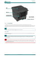
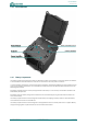
2.2.3 External Interfaces
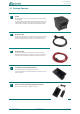
The External Interfaces will vary based on the options purchased when your GoBox was ordered.
The interface module presents both AC and DC connectors, combined transmit and receive antenna connector or separate
transmit and receive antenna connectors and/or an Ethernet port for use in Network mode.
2.2.3.1 AC Power Connector
The AC Power Connector interfaces to the AC Power Cable. The GoBox supports 100 – 250 VAC.
2.2.3.2 DC Power Connector
The DC Power Connector interfaces to the DC Power Cable. The GoBox supports 10.8 - 15.6 VDC.
2.2.3.3 Ethernet Connector
The Ethernet port is used to access the GoBox’s internal programming menu and/or to connect multiple GoBoxes via
Etherstack’s optional RNC switch.
Attach a standard Ethernet cable to this port with the other end connected directly to a laptop/PC or to other network
equipment. See Section 3.2 below for details on how to program you GoBox.
2.2.3.4 Tx/Rx Antenna Connector
The Tx/Rx Antenna Connector is of an N-Type connector and is to be connected to 3
rd
party antennas. For details of
approved transmit antenna types, refer to the section Approved Transmit Antennas.
! !! !
Do not attach an Ethernet cable to both Ethernet ports on the GoBox at the same time to a switch/router as it may
cause some network switches/routers to fail.
!
To achieve optimum performance, antennas should be setup according to antenna manufacture specifications,
including tuning of anten
nas, and appropriate mounting over ground planes.
!
Refer to the safety guidelines in the section Human Exposure to Radio Waves.
!