Profile User Manual v1.4.0 Rev A The Source Four LED series of fixtures are intended for professional use only. Read entire User Manual before using equipment. Copyright © 2013 Electronic Theatre Controls, Inc. A l l r i g h t s r es e r v e d . P r o d u c t i n f o r m a t i o n a n d s p e c i fi c a t i o n s s u b j e c t to c h a n g e . P a r t N u m b e r : 7460M1200-1.4.
E T C ® p e r m i ts t h e r e pr o d u c t i o n o f m a t e r i a l s i n t h i s m an u a l o n l y f o r n o n - c o m m e r c i a l p u r p o s e s . A l l o t h e r r i g h t s a r e r es e r v e d b y E T C . E T C i n t e n d s th i s d o c u m e n t , w h e t h e r p r i n te d o r e l e c t r o n i c , t o b e p r o v i d e d i n i t s e n t i r e ty . E T C i s a r e g i s t e r e d t r a d e m a r k o f E l e c t r o n i c T h e a t r e C o n tr o l s , In c .
Table of Contents Introduction . . . . . . . . . . . . . . . . . . . . . . . . . . 1 Quick Setups . . . . . . . . . . . . . . . . . . . . . . . . . . . . . . . . . . . . . . . . . . .1 Lustr+ . . . . . . . . . . . . . . . . . . . . . . . . . . . . . . . . . . . . . . . . . . . . . .1 Studio HD . . . . . . . . . . . . . . . . . . . . . . . . . . . . . . . . . . . . . . . . . . .1 Daylight and Tungsten . . . . . . . . . . . . . . . . . . . . . . . . . . . . . . . . .2 Fixture Components . . . . . . . . . . .
Safety Cable. . . . . . . . . . . . . . . . . . . . . . . . . . . . . . . . . . . . . . . . . . .26 Fixture Weight . . . . . . . . . . . . . . . . . . . . . . . . . . . . . . . . . . . . . . . . .26 Power and Data Cabling Requirements . . . . . . . . . . . . . . . . . . . . . .27 Power . . . . . . . . . . . . . . . . . . . . . . . . . . . . . . . . . . . . . . . . . . . . .27 Data. . . . . . . . . . . . . . . . . . . . . . . . . . . . . . . . . . . . . . . . . . . . . . .27 Connections . . . . . . . . . . .
Routine Maintenance . . . . . . . . . . . . . . . . . . . . . . . . . . . . . . . . . . . .78 Cleaning the Field Lens. . . . . . . . . . . . . . . . . . . . . . . . . . . . . . . .78 Inspecting and Cleaning the Electronics . . . . . . . . . . . . . . . . . . .79 Menu Flow Chart. . . . . . . . . . . . . . . . . . . . . 81 Home and Main Menus (Lustr+ and Studio HD) . . . . . . . . . . . . .81 Home and Main Menus (Daylight and Tungsten) . . . . . . . . . . . .82 Advanced Menu (Lustr+ and Studio HD) . . . . .
Introduction Congratulations on your purchase of a Source Four LED series by ETC product. Source Four LED series’s x7 Color System™ seven-hue technology produces a light and color quality that conventional LED systems cannot duplicate. This unique color system produces bright, broad-spectrum whites and intense colors equally well, rendering pigments, objects, and skin tones in a natural way. Daylight and Tungsten fixtures use high-output white LEDs for maximum brightness and efficacy.
Daylight and Tungsten Some of the options include: • Multiple dimming curve options. • Presets and sequences for standalone operation. • Strobe. • Loss-of-data behavior options. • Power regulation modes; three output options that offer a choice between maximum light output for lower duty cycles and maximum thermal stability and output consistency for higher duty cycles.
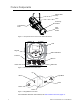
Fixture Components Safety cable loop Yoke Accessory retainer Yoke locking knob Color frame holder Figure-1.1 Components of the Source Four LED Profile Fixture. LCD Keypad Status indicators Power In DMX In Power Thru DMX Thru Figure-1.2 Components of the Rear Panel. Up Back Light Bulb Enter Home Down Figure-1.3 Keypad Button Functions. For information about the user interface, see User Interface Overview, page 37. 3 Source Four LED Profile v1.4.
Models Each member of the Source Four LED series product line is unique and optimized for a specific lighting task. All models are compatible with the complete line of Source Four Lens tubes.
Appl ications • • • • • Theaters Studios Schools Houses of worship Hotels • • • • Convention centers Theme parks Museums Temporary events Document Conventions Notices Throughout this manual, the following are used to alert you to notes and safety notices. Note: Notes are helpful hints and information that is supplemental ot the main text.
Safety The Source Four LED series fixtures are intended for professional use only. Read entire User Manual before using equipment. WARNING: Note: Introduction Note the following safety warnings before use: • Do not mount the Source Four LED series fixture on or near a flammable surface. • Do not use this fixture with a damaged power lead. If the power lead (cordset) is damaged, it must be replaced. • Do not use this fixture if glass lens is deeply scratched or cracked.
Contacts If you have questions about your Source Four LED series fixture that are not answered in this manual, please contact the supplier of your ETC equipment or ETC Technical Services. For general information, your most convenient resources are the references provided in this manual. To search more widely try the ETC web site at www.etcconnect.com. For technical questions about Source Four LED series fixtures, contact ETC Technical Services directly at one of the offices listed below.
Quick Start This section will help users to quickly use the Source Four LED fixture. For complete, detailed information and step-by-step instructions, see Operation, page 42. Install Step 1: Hang or mount the fixture using the provided hardware and approved hardware accessories. Step 2: Attach an approved safety cable when applicable. Step 3: Insert additional accessories (top hat, etc.) into the holder, if desired. Connect Step 1: Attach the power cable to the Power In connector.
Configure Set DMX Address Step 1: From the main screen, press [Enter] to open the Main Menu. Step 2: On the Main Menu, scroll to DMX Start Address and then press [Enter]. Step 3: Use [Up] or [Down] to scroll to the desired address. Step 4: Press [Enter] to select the address number. Step 5: Press [Home] to return to the home screen. A DMX address is not required if using standalone or master/slave control.
Quick Setups Menu Various pre-programmed combinations of operational settings are available to quickly get you started. These settings are specifically created for different situations and are easily accessible on the fixture’s user interface. Individual settings within each quick setup can be accessed via the Advanced menu in order to take advantage of all the possible control features. Quick Setups (Lustr+ and Studio HD) Step 1: On the Main Menu, scroll to Quick Setups. Step 2: Press [Enter].
Quick Setups (Daylight and Tungsten) Step 1: On the Main Menu, scroll to Quick Setups. Step 2: Press [Enter]. Step 3: Scroll to the desired setup and then press [Enter]. An asterisk (*) next to the setup name indicates that setup is active. Step 4: Press [Enter] to return to the home screen. The top line of the home screen displays the name of the active setup. Quick Setup Description Studio Video or film: The default setting for Daylight and Tungsten fixtures.
Chapter 1 Installation and User Interface Overview This chapter contains the following sections: 1 • Specifications. . . . . . . . . . . . . . . . . . . . . . . . . . . . . . . . . . . . . .13 • Hardware . . . . . . . . . . . . . . . . . . . . . . . . . . . . . . . . . . . . . . . . .16 • Aim Adjustments . . . . . . . . . . . . . . . . . . . . . . . . . . . . . . . . . . .18 • Installation Clearances . . . . . . . . . . . . . . . . . . . . . . . . . . . . . .
Specifications Physical • Rugged die-cast aluminum construction • Easy-access slots for secondary lenses and standard accessories.
Typical Power Consumption Lustr+ Idle Power / Current 100% Boost Power / Current 90V 4.27W / 0.084A 130.8W / 1.48A 120V 4.38W / 0.079A 129.9W / 1.11A 240V 4.2W / 0.068A 126.4W / 0.576A 100V 5.69W / 0.096A 129.2W / 1.3A 120V 5.71W / 0.091A 127.1W / 1.07A 240V 5.35W / 0.073A 126.2W / 0.564A 90V 4.3W / 0.083A 165.2W / 1.87A 120V 4.35W / 0.077A 163.3W / 1.39A 240V 4.04W / 0.066A 160.3W / 0.718A 100V 4.3W / 0.085A 159.8W / 1.81A 120V 4.35W / 0.078A 157.4W / 1.35A 240V 4.0W / 0.065A 154.8W / 0.
Color Rendering Index and Col or Quality Scale Ratings Source Four LED series fixtures are evaluated for Color Rendering Index (CRI) and Color Quality Scale (CQS) performance using measured output spectrum and optimized mix solutions for a best spectral match to black body sources at 3200K and 5600K. Color fidelity was also measured. These numbers may fluctuate slightly from fixture to fixture.
Hardware Basic Assembly Yoke Retainer bolt Shutters Pattern holder slot Drop-in iris slot Color frame Shutter barrel assembly Light engine body Lens tube Yoke locking knob Barrel rotation knob Beam focus knob Color frame holder NOTE: Safety cable is not included. Figure-1.1 Basic assembly. WARNING: Please note the following safety warnings before use: Do not mount the fixture on or near combustible surfaces. Do not operate the fixture without a lens installed.
Install Lens Tube Any of the ETC Source Four lens tubes can be installed into the shutter barrel of the Source Four LED Profile. For better results, use one of the preferred lens tubes listed below. Phillips screw Beam focus knob Figure-1.2 Secure lens tube with zoom knob and Phillips screw. Step 1: Slide the lens tube into shutter barrel. Step 2: Install the lens zoom knob. Step 3: Install the Phillips screw in the top of the lens barrel.
Aim Adjustments The fixture can be tilted up and down to aim the light where it is needed. The adjustment is the same for the yoke or floor stand. To assist aiming the fixture, you can turn it on without having to be connected to DMX control or enabling a preset. For more information, see Focus, page 55. Yoke locking knob Figure-1.3 Tilting the Fixture on the Yoke. Turning the Fixture On Step 1: Apply power to the fixture. Step 2: On the back of the fixture press [Light Bulb].
Focusing the Beam Beam focus knob Figure-1.4 Focusing the beam. Step 1: Loosen the beam focus knob located under the barrel as shown in Figure-1.4. Slide the lens tube forward or backward to achieve the desired beam edge. Step 2: Once the fixture is focused, tighten the beam focus knob. Shaping the Beam The beam can be shaped using the shutters (see Figure-1.1), a pattern, an optional drop-in iris, or by rotating the barrel.
Soft Focus Diffuser To clean up edge effects, use the soft focus diffuser in the A-size pattern holder. If combining the diffuser with a pattern, put the diffuser behind the pattern. The soft focus diffuser allows you to maintain sharp focus of the pattern while eliminating edge effects. The diffuser is intended for Source Four LED fixtures only. A permanent install kit is available. Figure-1.6 Soft Focus diffuser. Step 1: Install the diffuser into an A-Sized Pattern holder.
A c c e ss o r y Sl o t Accessory slot Iris Figure-1.7 Accessory slot The accessory slot is located on the top of the shutter barrel and in front of the pattern holder slot. It accommodates either a drop-in iris or a motorized pattern device. When the slot is not in use, a small sheet metal cover secured with two Phillips screws prevents light leakage. Step 1: Use a Phillips screwdriver to loosen the screws on the drop-in iris slot cover. Do not remove screws.
Adjusting the C-clamp For North America C-clamp Pan screw Pipe bolt Yoke bolt and lockwasher Figure-1.9 Adjusting the C-clamp. The C-clamp attaches the fixture to the mounting pipe and allows you to adjust the position of the fixture once it is mounted. Step 1: Tightly fasten the C-clamp to the yoke with the provided yoke bolt and lock washer. Step 2: Place the C-clamp on mounting pipe, then tighten the pipe bolt to secure it.
Adjusting the Yoke Position The Source Four provides multi-positioning capabilities within its yoke for overall fixture height and angle. Setting the Fixture Height Within the Yoke The Source Four has a two-position yoke for modifying the overall height in which the fixture is mounted. To change the height position, perform the following steps. General use position Low clearance position Figure-1.10 Adjusting the yoke position.
Installation Clearances C o o l i ng a n d D u t y C y c l e Desire series fixtures are fan cooled and can operate all channels at full power continuously in ambient temperatures up to 40°C (104°F). If ambient conditions exceed 40°C (104°F) or fail to allow sufficient airflow, over a long period of time, the fixtures may shut down and remain off until they return to a safe operating temperature. The fixtures provide two methods to indicate over temperature that can be set up on the Local Settings menu.
Dimensions and Hanging Clearances Use the following dimensions to allow proper clearances around the fixture. Allow additional space for cables. 10.6” 268mm 7.9” 200mm 24.2” 615mm 12.1” 308mm 17.1” 434mm 10.8” 274mm 6.9” 174mm 19.56” 497mm 13.3” 338mm 25.9” 659mm 30.7” 779mm 22.3” 566mm 13.1” 333mm 9.2” 233mm 12.9” 328mm Figure-1.11 Dimensions with typical 19°, 26° or 36° lens tube fully extended. Other lens tubes available, but not shown. 25 Source Four LED Profile v1.4.
Safety Cable A safety cable (or other approved safety device) should be attached to the fixture housing and wrapped around the hanging structure (pipe). An appropriate attachment loop is provided on the protruding tab of the fixture housing. Take care to leave as little slack as possible in the safety cable to avoid the cable catching the yoke of the fixture. Safety cable loop Figure-1.12 Safety Cable Loop on Fixture Housing.
Power and Data Cabling Requi rements Power The Desire series fixture operates on AC power, 100 to 240VAC/50-60Hz. The fixture must be connected to a non-dimmable power source in order to avoid damage to its internal power supply and other electrical components. CAUTION: The fixture must be connected to a non-dimmable power source in order to avoid damage to its internal power supply and other electrical components. Dimming will damage the fixture and void the warranty.
Connections All connections and user controls are located on the back of the fixture. Status indicators Power In DMX In Power Thru DMX Thru Figure-1.13 Power and DMX Connections on Back of Fixture. Connect AC input power and DMX data cables to the appropriate ports. Connect the incoming DMX data cable to the DMX Input connector. If you are daisy-chaining the data to other fixtures or DMX-controlled devices, connect the next DMX cable to the DMX Thru connector.
DMX Profile Addressing Addresses must be set between 1 and 510. Each Source Four LED series fixture must be considered a separate DMX device for the purpose of DMX line-loading calculations. DMX line-loading practice dictates that no more than 32 devices can be daisy-chained together. Consequently, no combination of Source Four LED series fixtures totaling more than 32 DMX devices should be configured in one DMX line.
Color Mixes The following table shows the color mixes for the fixture. Color 1 2 3 4 5 6 7 Lustr+ Red White Amber Green Cyan Blue Indigo Studio HD Red Red Orange Mint Blue Indigo — — HSI (Hue Saturation Intensity) and HSIC (Hue, Saturation, Intensity, Color Temperature (White Point)) The HSI profile uses 4 channels of DMX input, corresponding to 16-bit hue (two channels: coarse and fine), saturation, and intensity.
RGB Effectively addresses all 7 colors via three channels of control. The RGB profile produces medium-quality color crossfades. It makes the Source Four LED series fixtures compatible with conventional RGB console profiles while maintaining enhanced color production from the fixture. Also see Color Matching, page 32.
Plus 7 Plus 7 adds precision color-control channels to the HSI, HSIC, RGB, and Studio profiles. For example, HSI with Plus 7 enabled becomes a 15-channel profile. Placing channel 7 at a value over 51% activates the 15-channel profile within the fixture. The desired color and intensity is achieved by using the HSI or RGB channels as a starting point. Channels 8 to 14 represent the native LED colors of the fixture and allow you to adjust each color up or down in order to fine-tune the overall color output.
Daylight and Tungsten Profiles Direct Control The first DMX channel always controls Intensity from 0 to 100%. 1 2 Data Channel Fixture address Fixture address + 1 Intensity Strobe Control 3 Fixture address + 2 Fan control Value 0 to 255 Function Intensity 0 to 100% Variable strobe control Force fan on at various speeds Fan Control The Fan setting allows four options: DMX, Slow, Fast, and Automatic.
DMX Footpri nts and Channel Mapping Tungsten and Daylight Channel 1 Control Intensity 2 Strobe* 3 Fan control* Lustr+ and Studio HD Channel 1 2 3 4 5 HSI Hue Hue fine Saturation Intensity Strobe* HSIC Hue Hue fine Saturation Intensity Strobe* RGB Red Green Blue N/A Strobe* Studio Intensity Color temp Tint N/A Strobe* Direct Color 1 Color 2 Color 3 Color 4 Color 5 Fan control* Color temp Fan control* N/A Fan control* N/A Color 6 7 Fan control* N/A 8 on/off* on/off* on/off* on/off* Inte
Installing Accessories Color Frame Holder Retaining clip in the locked position Figure-1.14 Color frame holder and retaining clip. The gel frame holder is equipped with a spring-loaded retaining clip that prevents gel frames and accessories from falling out. WARNING: Make sure all color frames and accessories are locked in position with the retaining clip before hanging the fixture. Step 1: Release the retaining clip by pushing it sideways while gently pulling backwards.
Chapter 2 Basic Menu Navigation This chapter contains the following sections: 2 • User Interface Overview . . . . . . . . . . . . . . . . . . . . . . . . . . . . .37 • LCD . . . . . . . . . . . . . . . . . . . . . . . . . . . . . . . . . . . . . . . . . . . . . .37 • Screen Navigation . . . . . . . . . . . . . . . . . . . . . . . . . . . . . . . . . .39 • Status (Home) Screens . . . . . . . . . . . . . . . . . . . . . . . . . . . . . .40 • Menu Navigation . . . . . . . . . . . . . . . . . . . .
User Interface Overview The Source Four LED series user interface (UI) consists of an LCD and keypad. All of the basic information is displayed on the LCD and the keypad is used to navigate through the menus. Use the LCD and keypad to program the fixture for your specific application. LCD Keypad Status indicators Figure-2.1 User Interface on back of fixture. LCD The Source Four LED series fixture features a backlit LCD capable of displaying 8 rows of text with 21 characters per line.
Keypad Use the keypad buttons to access and navigate the menus on the LCD. Figure-2.2 Keypad buttons. Home Opens the home screen. Back Cancels the current operation and returns to the previous screen. Multiple presses of the back button will eventually take you to the status display. Up Increases a value or menu choice by one. Pressing and holding the push button increases the rate of change. Down Decreases a value or menu choice by one. Pressing and holding the push button increases the rate of change.
Status Indicators Figure-2.3 Status Indicators on the back of the fixture. The status indicators are three, small, colored LEDs on the User Interface that indicate the status of: • Power — Illuminated blue when AC power is supplied to the fixture. • DMX — Illuminates green when an active DMX signal is being received by the fixture. • Error — Illuminates red only when the fixture is experiencing a data error, high internal temperature, or other abnormal condition. Status indicators are on by default.
Status (Home) Screens The status (home) screens display when you press [Home] or when there is no activity for a specific time. The home screens display the status of multiple fixture settings.
System Message Area Displays status messages, which vary depending on the function that is currently active. Master or Slave Indicates if the fixture is the master or slave when the a string of fixtures is running together in standalone operation. For more information, see Master/Slave Operation, page 64. Sequence Indicates whether or not a sequence is active and if so, which sequence is active. For more information, see Presets & Sequences, page 55.
Chapter 3 Operation This chapter contains the following sections: 3 Operation • Home Screen Displays . . . . . . . . . . . . . . . . . . . . . . . . . . . . . .43 • Main Menu . . . . . . . . . . . . . . . . . . . . . . . . . . . . . . . . . . . . . . . .45 • Advanced Menu . . . . . . . . . . . . . . . . . . . . . . . . . . . . . . . . . . . .47 • Studio Settings. . . . . . . . . . . . . . . . . . . . . . . . . . . . . . . . . . . . .73 • Error Messages . . . . . . . . . . . . . . . . . . . . .
Home Screen Displays Depending on the fixture settings, the following are displayed in the system message area on the respective home (status) screens.
Fan Control The fan can be forced on via DMX control or by adjusting settings under the Advanced Settings menu. For more information, see Fan Control, page 33. Thermal Shutdown Warning Displayed as OverTemp, it is what the fixture does to visibly warn you that it has become overheated and has gone into a shut-down status, which is maintained until the fixture returns to a safe operating temperature. For more information, see OverTemp, page 71.
Main Menu The Main Menu can be accessed at any time while viewing other screens. To access the Main Menu, press [Home] and then press [Enter]. DMX Start Address Use the DMX Start Address to set the DMX address of the fixture. Also see DMX Settings, page 47. Main Menu DMX Start Address: Quick Setups Advanced Settings Main Menu DMX Start Address: Quick Setups Advanced Settings 001 001 Figure-3.1 Selecting DMX Start Address on the Main Menu. Step 1: On the Main Menu, scroll to DMX Start Address.
Advanced Settings The Advanced Settings menu is for experienced users or for applications that entail very carefully defined performance parameters. You can make individual adjustments of all fixture settings for customized control. Main Menu DMX Start Address: Quick Setups Advanced Settings 001 Advanced Menu DMX Settings LED Settings Presets and Sequences Diagnostics Local Settings Copy All Settings Figure-3.3 Advanced Menu from the Main Menu.
Advanced Menu The Advanced Menu provides access to various fixture settings and specific operations. The Advanced Menu is accessed from the Main Menu by pressing [Up] or [Down] to select Advanced Settings and then pressing [Enter]. Copy All Settings appears on the screen only when DMX is not present. See Copy All Settings, page 72. DMX Settings The current DMX settings are shown in the DMX Settings screen.
DMX P rofile The current DMX profile is displayed on the DMX Settings menu. You can customize the setting by selecting a different profile. For detailed information about each profile, see Profiles, page 29. Step 1: On the DMX Settings menu, scroll to DMX Profile. DMX Settings DMX Start Address: DMX Profile: Strobe: Data Loss: Plus Seven: DMX Profile: 3/15 Saturation 101 HSIC Enabled Instant Enabled 6 chan Figure-3.5 Selecting DMX Profile on the DMX Settings Menu.
Fan Control Fan Control adds another DMX channel of control when set to DMX. Alternate settings are Slow, Fast, and Automatic. For more information, see Fan Control, page 33. Step 1: On the DMX Settings menu, scroll to Fan. DMX Settings DMX Start Address: DMX Profile: Strobe Mode: Data Loss: Fan Mode: 101 Direct Enabled Instant Auto 6/15 Fan Figure-3.7 Setting the Fan Mode on the DMX Settings Menu. Step 2: Press [Enter] to scroll through the available options.
Plus Seven (Lustr+ and Studio HD) Plus Seven allows enhanced color-mixing precision when using the RGB, HSI, HSIC, or Studio profile as a starting point for color selection. Enabling Plus Seven adds another 8 DMX channels of control at the end of the control channels already in use by the fixture. For example, in the HSIC profile, with Strobe enabled, the fixture uses 6 channels of control. Enabling Plus Seven adds another 8 channels to the fixture, for a total of 14 channels of control.
N O T E : Once any one of the seven individual color channels is altered from its neutral starting position, the settings for the original color point may no longer reflect the actual output of the fixture. When using RGB, HSI, HSIC, or Studio profile for color selection, each fixture makes accommodations for the specific LEDs in its array and produces output that is consistent with other fixtures, whether or not they use LEDs from the same production batch.
Boost Boost provides the brightest possible output, with least guarantee of consistency. This is best for applications with low duty cycles, loose brightness requirements, or where ambient temperature is low. Step 1: On the Advanced Menu, scroll to LED Settings. Step 2: Press [Enter]. Step 3: With Output selected, press [Enter] to toggle between the options. Step 4: Press [Up] or [Down] to commit the option.
Linear Intensity Linear has no curve. Brightness levels correlate exactly with the value of the dimming control signal. Moderate lag in response for good dimming smoothness. Linear allows quick jumps in brightness. It is best for studio lighting and applications with static scenes or looks. 0 DMX 255 Quick Intensity Quick uses the standard dimming curve but with no lag or smoothing. All changes are instant and correlated exactly with the control input signal.
Output Freq Output Frequency is the frequency in Hz at which the LED array pulses, or blinks, as a function of Pulse-Width Modulation (PWM). The frequency is adjustable in order to avoid visible flicker on video and film. When altering the frequency in order to reduce noticeable flicker on camera, often only a small change is required. The range is 920 to 1500 Hz in increments of 10. The default value is 1200 Hz. For high speed exposure or rolling shutter cameras, use the High 25K mode.
White Point (Lustr+ and Studio HD) White Point controls the appearance (color temperature) of white-light output when saturation is at or near zero. This option is available when using the HSI and RGB profiles. The choices are 2950K, 3200K, 5600K, and 6500K. Step 1: On the LED Settings menu, scroll to White Point. LED Settings Output: Regulated Curve: Standard Output Freq: 1200 Red Shift: Off White Point: 3200K Figure-3.14 Selecting White Point on the LED Settings Menu.
Presets (Lustr+ and Studio HD) A Preset is a single, static look or color mix. The Source Four LED series fixture comes with 24 default configurations. Only one Preset can be active at a time. You can activate any of the Preset color mixes and customize each one. The following table lists the default Preset color mixes.
Presets and Sequences Focus: Presets Sequences Off Preset 1 is Active No Sequence is Active Presets Preset: Status: Fade Time: Delay Time: Edit Color Copy to Other Fixture Save DMX as Preset * 23 Active 00:02 00:00 Figure-3.16 Selecting Presets on the Presets and Sequences Menu. Note: Step 1: On the Presets and Sequences menu, scroll to Presets. Step 2: Press [Enter]. Step 3: With Preset selected, press [Enter]. Step 4: Press [Up] or [Down] to set the desired preset number.
Delay Time Delay time is the length of time the fixture waits on the previous setting before initiating the crossfade to the Preset. The default is 0 seconds. Step 1: On the Presets menu, scroll to Delay Time and press [Enter]. Presets Preset: Status: Fade Time: Delay Time: Edit Color Copy to Other Fixture Save DMX as Preset * 23 Active 00:02 00:00 Figure-3.18 Selecting Delay Time on the Presets Menu. Step 2: Press [Up] or [Down] to set the desired time in minutes. Step 3: Press [Enter].
Edit (Daylight and Tungsten) Use Edit to change the brightness and strobe settings of the LED array. To keep your changes, be sure to select Save Changes and then press [Enter]. To discard changes press [Back] at any time. If the Preset is currently active, the changes made on the Preset Edit screen update to the fixture output immediately. Step 1: On the Presets menu, scroll to Edit and press [Enter]. Preset 23 Edit Preset: Int: Strobe: Save Changes 23 100% 0 Figure-3.20 Edit Preset Screen.
Presets Preset: Status: Fade Time: Delay Time: Edit Color Copy to Other Fixture Save DMX as Preset * 23 Active 00:02 00:00 Figure-3.22 Save the DMX as a Preset. Step 2: With Preset selected, press [Enter]. Step 3: Press [Up] or [Down] to set the desired preset number. Step 4: Press [Enter]. Step 5: Scroll to Save DMX as Preset and press [Enter]. Sequences A Sequence is a timed series of presets. Up to 12 different Sequences may be altered for Preset selections, crossfade rate, and link time.
A Rate of 100% represents running the Sequence with timing exactly as specified within the Presets. A Rate above 100% represents running the Sequence with faster timing than specified within the Presets. For example, with a Rate of 200%, a Preset with a Fade Time of 6 seconds would actually be run within the Sequence in only 3 seconds. A Rate below 100% represents running the Sequence with slower timing than specified within the Presets.
Preset Preset is the number of a Preset, whether it is a predefined or a custom color mix. Step 1: On the Sequences menu, scroll to Preset and press [Enter]. Sequences Sequence: Status: Rate: Step: Preset: Link Time: 00:02 Copy to Other Fixture * 3 Active 100% 01 1 Step 2: Selecting Preset on the Sequences Menu. Step 3: Press [Up] or [Down] to set the desired Preset number. Step 4: Press [Enter]. Step 5: Press [Down] to scroll to Link Time.
Finishing the Sequence After each of the steps have been configured, set the End State. End state is what the fixture does once it completes the Sequence. Two end state options are available and both options repeat indefinitely until the Sequence is deactivated. To access the end state options, you must first program an additional and final step within the sequence using Preset 0. Preset 0 marks the end of the Sequence and opens the End State menu line. Preset 0 may only be used once within a Sequence.
Copy to Other Fixtures If other fixtures are connected to the same data chain, you can copy the Sequences settings to the other fixtures. The fixture automatically becomes the Master and controls all the other fixtures (Slaves) in the chain until another fixture has its Preset or Sequence settings selected or activated. For more information, see Master/Slave Operation, page 64. Step 1: On the Sequences screen, scroll to Copy to Other Fixtures.
Slave Any fixture in the data chain that is being controlled by the master fixture. By default, all fixtures are slaves, except the one that had its Preset or Sequence altered most recently. A Slave fixture can only directly imitate the performance of the Master fixture. When operating as a Slave fixture, the fixture displays Slave on its home screen. Diagnostics The Diagnostics menu provides access to detailed information about various aspects of the fixture’s performance.
Network Statistics The Network Statistics screen displays the statistics of the network. The DMX input values dynamically change. This screen is read-only. Step 1: On the Diagnostics screen, scroll to Network Statistics. Step 2: Press [Enter]. When you access the screen, the dynamic values start at 0 and continue to increase. Diagnostics Network Statistics Overruns: Received: Breaks: Bad Starts: DMX Starts: RDM Starts: 0 47835 15490 0 27120 0 Figure-3.32 Network Statistics Screen with Dynamic values.
Chase Chase automatically sequences through each LED color and starts each at 0% intensity and steps up to 100% before moving to the next color. You can set the number of steps per second for sequencing through all LED colors individually. Step 1: On the Test screen, scroll to Action. Step 2: Press [Enter] until the Chase option displays. The fixture begins to sequence through the LEDs. Step 3: Press [Down] to select Chase. Step 4: Press [Enter] to select the values.
R e c a l i b r at e F ix t u r e Service technicians may use this option to calibrate the constant current driver electronics for the LEDs. The calibration process goes through each series of LEDs, starting at 0 intensity and stepping up to 100%. The calibration is automatic and takes a few minutes. During this time, do not exit the screen until it is complete. CAUTION: This calibration process does not measure or recalibrate the light output of the LEDs.
Local Settings The Local Settings menu gives you several options that affect the LCD and other functions of the fixture. Local Settings Backlight: 100% BLght time out: 1 min Language: English Status Indicators: Off OverTemp: Visible Restore Defaults Advanced Menu DMX Settings LED Settings Presets and Sequences Diagnostics Local Settings Copy All Settings Figure-3.37 Selecting Local Settings on the Advanced Menu. Step 1: On the Advanced Menu, scroll to Local Settings. Step 2: Press [Enter].
Language Use this to select the language that is used for all menus. The options are English, Spanish, French, and German. The default is English. Step 1: With Language selected, press [Enter]. Local Settings Backlight: 100% BLght time out: 1 min Language: English Status Indicators: Off OverTemp: Visible Restore Defaults Figure-3.39 Setting the Screen Language. Step 2: Continue to press [Enter] until the desired language is displayed. Step 3: Press [Up] or [Down] to commit the option.
O ve r T e m p You can change how an over-temperature situation is indicated in order to control stray light. Visible (Lustr+ and Studio HD) The fixture produces a low-level, red light from the LED array, displays a warning message on the LCD, turns on the LCD backlight, and turns on the error indicator light.
Copy All Settings When DMX is not applied you can copy all, except DMX address, settings globally to all of the other fixtures in the same data chain in one step. This includes everything from Presets and Sequences to Quick Setups and Advanced options. This feature is not available when DMX is applied to the fixture. Advanced Menu DMX Settings LED Settings Presets and Sequences Diagnostics Local Settings Copy All Settings Figure-3.42 Copy All Settings on the Advanced Menu.
Studio Settings Lustr+ and Studio HD The Studio profile produces only white light that is adjustable in brightness, white point, and tint (green/magenta balance). The Studio profile can be operated in a stand-alone mode from the user interface or can be controlled via DMX.
Studio DMX Control When controlled via DMX, the first three channels adjust the output in the following order. Channel 5 controls strobe. Channel 1 2 3 5 Output Intensity (Brightness) White Point Tint Strobe When adjusting white point via DMX, the full gamut of 2700 to 6500K is available, but common settings of 3200K and 5600K are quickly accessible at the lowest and highest DMX values, respectively. The range of control on channel 2 is distributed as follows.
Daylight and Tungsten The Studio profile allows quick adjustment of Intensity. The Studio profile can be operated in a stand-alone mode from the user interface or can be controlled via DMX. Operation From Home Status Screen (Studio Standalone) When operating without an external control signal, the quality of the white light can be adjusted immediately and directly by pressing the UI buttons on the fixture while on the home screen. In this setup, all the UI buttons change their functions from other setups.
Error Messages When a system error is detected, a message displays on the home screen. The message changes to reflect the specific error type. When multiple errors are detected, each error message cycles, in increasing numerical order on the display for 1 second each. The following table lists the error messages.
Software Updates The software can be updated with UpdatorAtor Software. UpdatorAtor allows you to remotely update the Source Four LED fixture. UpdatorAtor is installed on your computer and connected from the computer to the fixture with a special cable. For more information, contact ETC’s Technical service department. ETC Technical Support Any time, any day–15 minute response time—that’s our service commitment. ETC’s Technical Service is unparalleled in the industry.
Routine Maintenance To ensure optimum performance of your Source Four LED series fixture, you should perform the following inspections and cleaning at least once a year. You may need to inspect or clean the fixture more often, depending on the type and amount of use your fixture experiences during the year. WARNING: Allow fixture to cool down completely prior to cleaning. Disconnect all power and DMX cables prior to cleaning.
I n s p e c t i n g a n d C l e a ni n g t h e E l e c t r o n i c s A can of compressed air or oil-free air from an air compressor set at a low setting can be used to blow through the vent holes and remove dust or other debris from the interior of the fixture. Dust buildup can cause overheating and premature shutdown. Remove the secondary lenses (if used) and clean out any dust and debris.
80
Appendix A Menu Flow Chart The following illustrations show each of the menus that are displayed on the Desire series fixture LCD and the path to each one.
Home and Main Menus (Daylight and Tungsten) Stage Dir Reg Stnd –– Str Master No Sequence is Active No Preset is Active System OK 1/3 Intensity Main Menu DMX Start Address: Quick Setups Advanced Settings Main Menu DMX Start Address: Quick Setups Advanced Settings 001 001 Quick Setups *Studio Stage Single Channel 1/3 Intensity Main Menu DMX Start Address: Quick Setups Advanced Settings A Menu Flow Chart 001 To Advanced Menu 82
Advanced Menu (Lustr+ and Studio HD) Main Menu DMX Start Address: Quick Setups Advanced Settings 001 Advanced Menu DMX Settings LED Settings Presets and Sequences Diagnostics Local Settings Copy All Settings * DMX Settings DMX Start Address: 101 DMX Profile: HSIC Strobe: Enabled Data Loss: Instant Plus Seven: Enabled DMX Profile: 6 chan 1/15 Hue Coarse LED Settings Output: Regulated Curve: Standard Output Freq: 1200 Red Shift: Off White Point: 3200K Advanced Menu DMX Settings LED Settings Presets and S
Advanced Menu (Daylight and Tungsten) Main Menu DMX Start Address: Quick Setups Advanced Settings 001 DMX Settings DMX Start Address: DMX Profile: Strobe Mode: Data Loss: Fan Mode: Advanced Menu DMX Settings LED Settings Presets and Sequences Diagnostics Local Settings Copy All Settings * 101 Direct Enabled Instant Auto 1/15 Intensity LED Settings Output: Regulated Curve: Standard Output Freq: 1200 Advanced Menu DMX Settings LED Settings Presets and Sequences Diagnostics Local Settings Copy All Setti
Presets Menu (Lustr+ and Studio HD) Advanced Menu DMX Settings LED Settings Presets and Sequences Diagnostics Local Settings Copy All Settings * Copy All Settings appears only when DMX is not present.
Presets Menu (Daylight and Tungsten) Advanced Menu DMX Settings LED Settings Presets and Sequences Diagnostics Local Settings Copy All Settings * Copy All Settings appears only when DMX is not present.
Sequences Menu Presets and Sequences Focus: Presets Sequences Off Preset 1 is Active No Sequence is Active Sequences Sequence: Status: Rate: Step: Preset: Link Time: 00:02 Copy to Other Fixture Sequences Sequence: Status: Rate: Step: Preset: Link Time: 00:02 Copy to Other Fixture Sequences Sequence: Status: Rate: Step: Preset: Link Time: 00:02 Copy to Other Fixture * 3 Active 100% 01 1 * 3 Active 100% 01 1 * 3 Active 100% 01 1 Sequences Sequence: Status: Rate: Step: Preset: Link Time: 00:02 Copy to O
Diagnostics Menu Advanced Menu DMX Settings LED Settings Presets and Sequences Diagnostics Local Settings Copy All Settings Diagnostics Current DMX In Network Statistics Test Recalibrate Fixture About Fixture Diagnostics Current DMX In Network Statistics Test Recalibrate Fixture About Fixture Diagnostics Current DMX In Network Statistics Test Recalibrate Fixture About Fixture Diagnostics Current DMX In Network Statistics Test Recalibrate Fixture About Fixture Diagnostics Current DMX In Network Statisti
Diagnostics Test Advanced Menu DMX Settings LED Settings Presets and Sequences Diagnostics Local Settings Copy All Settings Diagnostics Current DMX In Network Statistics Test Recalibrate Fixture About Fixture Diagnostics Test Action: Chase Chase: 15 steps/sec Individual Control G O R A O R I 00 00 48 00 00 00 00 Diagnostics Test Action: Chase Chase: 15 steps/sec Individual Control G O R A O R I 00 00 48 00 00 00 00 Diagnostics Test Action: Ind Cntr Chase: 15 steps/sec Individual Control G O R A O R I
Diagnostics Recalibrate Fixture Advanced Menu DMX Settings LED Settings Presets and Sequences Diagnostics Local Settings Copy All Settings Diagnostics Recalibrate Fixture This Will Calibrate LED Array Diagnostics Current DMX In Network Statistics Test Recalibrate Fixture About Fixture Are You Sure? Yes No LED LED LED LED LED LED LED A Menu Flow Chart 1 2 3 4 5 6 7 LED Calibration .......Pass .......Pass .......Pass .......Working .......Working .......Working .......
Corporate Headquarters 3031 Pleasant View Road, P.O.