
User Manual


2 The Retrofit 7
Section 2
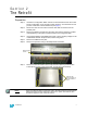
The Retrofit
Preparation
Step 1: Use Sensor Configuration Editor and a SLTA to download and save the current
Sensor configuration out of the pack for later reference. For information on this
process contact ETC Technical Services (see page 1).
Step 2: Disconnect all of the Cam-Lok
®
connectors and data connections from the
portable pack.
Step 3: Remove the dimmer modules from the pack. Note and document the modules’
order/positioning in the pack for proper insertion and configuration later.
Step 4: Use a digital voltmeter and VERIFY that power is off by checking voltages for all
combinations between the phase bars, neutral and ground.
Step 5: Remove the CEM from the pack.
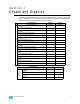
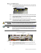
Step 6: Remove the pack door using a #2 Phillips-head screwdriver.
Step 7: Remove the four black side covers. They are held in place by 24 5/32” allen
screws (three on each corner of the pack, on both the top and bottom).
Note:
If your pack has the Cam-Lok pass thru option, the side panels are secured at the
bottom with extra long hex head bolts. These are in place of the bottom allen
screws and require a 7/16” socket to remove.
Remove hinge
screws
Remove side
retainer screws on
top and bottom of
pack