
User Manual


2 The Retrofit 13
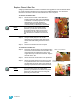
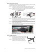
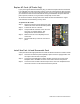
Step 7: Connect the dimmer output cable to the appropriate connector on the rear of the
backplane. For portable packs, use the lower connector, closest to the center of
the backplane. Make sure the “INSTALL THIS SIDE UP” label on the transition
card is visible from above.
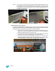
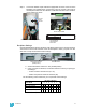
Backplane Settings
Upgrade kit backplanes ship from the factory with all DIP switches in the off (down) position.
You will have to set the DIP switches on the new backplane to match your pack. You will
also have to verify the termination switch settings.
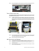
a: Set both termination switches to “Off” (middle position).
b: Using a precision screwdriver, set the DIP switches to match your pack type
according to:
• number of dimmer module slots (6 or 12)
• whether the pack has Advanced Features (AF)
Use the following chart to determine your required DIP switch settings:
“On” position = switch pushed to the top
DIP switch Number
Pack Model 12345678
SP12 (6 slots) On On
SP12 AF (6 slots) On On On
SP24 (12 slots) On
SP24 AF (12 slots) On On
Bundle wires and tuck into pack frame
Connect
Power
Harness
Dimmer Output Cable
Connect Dimmer
Output Cable to
this location
Rear of backplane
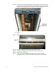
Set termination to “Off”
(middle position)
Set DIP switches