
User Manual


12 CEM3 Sensor Portable Pack Retrofit Manual
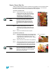
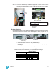
Step 4: Secure the backplane in place using the new screws and collars provided in the
kit. Screw holes are in the top corners of each arm of the backplane.
Convert Dimmer Output Cable
The upgrade kit includes an transition card to adapt the old dimmer output connector to the
new backplane connectors. This card is labeled as a “LOWER CARD” indicating the lower
connector slot that it will connect to.
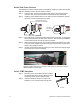
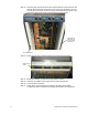
Step 1: Install the transition card into the old dimmer output cable connector. Align the
transition card and ribbon cable so that the red-striped wire of the ribbon cable
lines up with pin-1 on the card. Pin-1 is indicated by a downward arrow on the J2
side of the connector (see below). Make sure the card is fully seated in the old
connector.
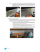
Step 2: Secure the transition card in the connector using two 4” wire ties. There is a notch
on the left and right sides of the card for the wire ties to rest in. Try to align the
wire tie stub behind the flat edge of the connector.
Step 3: Trim the ends of the wire ties for neatness.
Add Connections to the Backplane
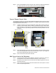
Step 4: Connect the power wire harness adapter to the power connector on the rear of
the backplane. The connector is keyed and will only connect one way.
Step 5: Bundle any excess wires from the power harness adapter together and secure
them with a wire tie.
Step 6: Trim the end of the wire tie and tuck the bundle into the vacant punch out in the
side of the pack support frame.
Be sure to use collars
Align red
wire with
“pin-1”
on card
Notch for wire tie
Wire tie
through
notch
Slide card into connector
Arrow
indicates
pin-1
Align wire tie stub
behind connector