
User Manual


2 The Retrofit 11
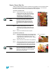
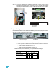
Step 3: Once in place, insert the clips on the arms into their respective locations in the
pack metal and then slide the backplane forward so that the clips stay in place.
The backplane is far enough forward when the screw holes in the upper corners
are visibility not insert the screws yet as you may need to partially remove the
backplane in a later step
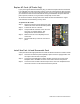
Grounding the power harness
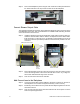
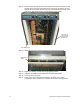
On the rear of the backplane, you will find an open screw hole near the bottom of the metal,
between the CAT5 connector and the blue DMX connector. This is the intended location for
landing the green ground wire from the power wire harness adapter.
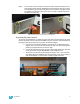
a: Cut the power wire harness adapter’s ground wire to an appropriate length
(approx. 8”) to connect to the open screw hole. Strip 1/2” of the 18 gauge wire
jacketing to expose bare wire for the next step.
b: Connect the provided ring crimp connector (ETC Part# J434) to the bare end
of the ground wire using a T&B ERG2001 or WT112M hand tool.
c: Secure the ring connector to the backplane using the 6-32 x 1/4” screw with
lock washer (ETC part # HW213) from the upgrade kit. It may be necessary to
raise the backplane out of its location in order to tighten the screw.
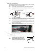
Slide arm clips in place to ensure proper screw alignment
Connect ground wire to this location using screw and washer from kit