
User Manual


8 CEM3 Sensor Portable Pack Retrofit Manual
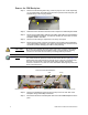
Remove the CEM Backplane
Step 1: Remove the lid retaining bolts using a wrench (may be 7/16” or 3/8” depending
on your pack model). The bolts are found at the top of each side of the pack, just
beneath the lip of the carrying handles.
Step 2: Raise the lid from the data connection side to expose the CEM backplane metal.
Step 3: Disconnect the DMX ribbon cable and the analog data cable from the backplane
using a #2 Phillips screwdriver. You will have to back the connectors out of the
backplane metal to free them.
Step 4: Remove the lid entirely to expose the inner cavity of the pack.
Step 5: Disconnect the power connector and dimmer output cable from the backplane
using a #2 Phillips screwdriver. Use caution when backing the connectors out of
the metal to prevent damaging the cables’ outer jacketing.
Step 6: Remove the backplane screws found at the top corners on each side of the
backplane using a #2 Phillips screwdriver.
Step 7: Bend in the side arms of the backplane and remove the CEM backplane from the
pack.
CAUTION:
Be careful not to damage the outer jacket of the power or dimmer output wires
when removing them from the backplane metal. If you damage the jacketing,
contact ETC Technical Services before proceeding with the procedure.
Note:
Check to see if the power connector is damaged or disfigured from previous use.
If so, it will need to be replaced. Contact ETC technical Services (see page 1) for
replacement parts and instructions. Damage to this connector is typically in the
form of a crack in the left or right side of the plastic housing of the power
connector. Presence of a crack can cause intermittent rebooting and power loss
to the control electronics
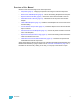
Up
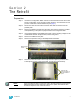
Side View of Pack
Disconnect these from Backplane
Power
Dimmer Output
Backplane screw
DMX
Analog
Backplane screw