® Sensor Portable Pack (SP Series) CEM to CEM3 Retrofit Manual Revision B C o p y r i g h t © E le c tr o n i c T h e a t r e C o n t r o l s , I n c . All Rights reserved. P r o d u c t in f o r m a t i on a n d s p e c i f i c a t i o n s s u bj e c t t o c h a n g e .
E T C p e r m i t s t h e r e p r o d u c t i o n o f m a t e r i a l s i n t h i s m a n u a l o n l y f o r n o n - c o m m er c i a l p u r p o s e s . A ll o t h e r r ig h t s a r e r e s e r v e d b y E T C . ET C ®, a n d S e n s o r ® a r e r e g i s t e r e d t r ad e m a r k s o f E l e c t r o n i c T h e a t r e C o n tr o l s , I nc . i n t h e U n i t e d S t a t e s a n d o th e r c o u n t r i e s .
Introduction This manual is intended to guide ETC Service Technicians through the process of upgrading existing Sensor® Portable Packs to Sensor3 Portable Packs with a CEM3 control module. This manual covers SP12 and SP24 portable packs. Contacting Technical Services If you have questions about the retrofit process that are not answered in this manual, please contact ETC Technical Services.
Other Retrofit Kits This retrofit kit is for upgrading a Sensor CEM portable pack to a CEM3 portable pack. Other kits are available for retrofitting other Sensor and Sensor+ dimming products.
Overview of this Manual Reference this manual throughout the retrofit procedure.
4 CEM3 Sensor Portable Pack Retrofit Manual
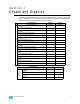
Section 1 Unpack and Organize Parts/Components ETC Part Number Phase Connector Top/Bottom 7052A3015 Phase Connector Top/Bottom 7052A3081 CEM Classic to CEM3 Backplane Power Adapter Harness 7141B7010 Sensor3 Pack Top Cover Assembly 7142A2005 Sensor3 Pack Backplane Assembly 7142A2006-CFG Sensor Portable Pack CEM Classic to CEM3 Retrofit Manual 7142M2310 16 pin power transition PCB 7150B4009A Dimmer Output Lower Ribbon Card LF Assembly 7150B5606 Backplane DMX PCB Cable 7152B8001 Screw 6-32 x .
Required Tools #1 Phillips screwdriver #2 Phillips screwdriver 3/8” socket 7/16” socket 5/32” Allen wrench 7/16” wrench 3/8” wrench Heat gun Diagonal wire cutter Permanent marker Crimp tool for ring terminal splice (T&B ERG2001or WT-112M hand tool) Wire strippers 6 CEM3 Sensor Portable Pack Retrofit Manual
Section 2 The Retrofit Preparation Step 1: Use Sensor Configuration Editor and a SLTA to download and save the current Sensor configuration out of the pack for later reference. For information on this process contact ETC Technical Services (see page 1). Step 2: Disconnect all of the Cam-Lok® connectors and data connections from the portable pack. Step 3: Remove the dimmer modules from the pack. Note and document the modules’ order/positioning in the pack for proper insertion and configuration later.
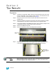
Remove the CEM Backplane Step 1: Remove the lid retaining bolts using a wrench (may be 7/16” or 3/8” depending on your pack model). The bolts are found at the top of each side of the pack, just beneath the lip of the carrying handles. Up Side View of Pack Step 2: Raise the lid from the data connection side to expose the CEM backplane metal. Step 3: Disconnect the DMX ribbon cable and the analog data cable from the backplane using a #2 Phillips screwdriver.
Replace Phase A Bus Bar A slightly modified Phase A bus bar is included in the upgrade kit. This new bus bar allows for greater clearance between the bus bar and the CEM3 backplane. You will need to remove the old Phase A bus bar and install the new one in its place. To remove the old bus bar: Step 1: Note: Disconnect the Phase A Cam Wire and Phase A Detection Wire using a #2 Phillips screwdriver or socket (may be 7/16” or 3/8” depending on your pack model) as required.
Attach New Power Harness The upgrade kit contains an edge connector (straight thru PCB) and a power wire harness adapter to transition power to the new power connector. Step 1: Insert the edge connector (straight thru PCB) into the old backplane power connector. The connector is the same on both sides and top and bottom. Step 2: Install the power adapter harness to the edge connector (straight thru PCB) to old power connector (match the wire colors) . The PCB is the same on both sides, top and bottom.
Step 3: Once in place, insert the clips on the arms into their respective locations in the pack metal and then slide the backplane forward so that the clips stay in place.
Step 4: Secure the backplane in place using the new screws and collars provided in the kit. Screw holes are in the top corners of each arm of the backplane. Be sure to use collars Convert Dimmer Output Cable The upgrade kit includes an transition card to adapt the old dimmer output connector to the new backplane connectors. This card is labeled as a “LOWER CARD” indicating the lower connector slot that it will connect to. Step 1: Install the transition card into the old dimmer output cable connector.
Step 7: Connect the dimmer output cable to the appropriate connector on the rear of the backplane. For portable packs, use the lower connector, closest to the center of the backplane. Make sure the “INSTALL THIS SIDE UP” label on the transition card is visible from above.
Replace AF Cards (AF Packs Only) If your pack supports Advanced Features (AF) you will need to replace the AF card as well. If you identified your pack as AF when ordering, a new AF card should have been sent with your upgrade kit. If you do not have the new AF card, you may continue with the retrofit and you can add AF cards at a later date without having to disassemble the pack. While the pack is opened, however, it is a good time to easily swap out the cards.
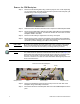
Step 9: Peel the backing off of the provided plastic wire retainer clip and stick it to the center of the underside of the pack lid. Slide the DMX cable and the CAT5 cable into the retainer clip... Step 10: Lower the pack lid into place in a closed position. Step 11: Secure the pack lid in place using the bolts and washers removed earlier. Use three bolts and washers per side (6 total).
Step 12: Place the pack side rails back into their original locations and secure them with the 5/32” allen screws removed earlier. three screws top and bottom, for each side rail (24 screws total). Be sure to put the side rail with the door hinge screw holes in the appropriate location, opposite the door latch retainer. Place side rail with door hinge screws holes in this location. Door latch retainer Step 13: Attach the new door to the side rail using the screws removed earlier.
Corporate Headquarters 3031 Pleasant View Road, P.O.