® CE Sensor Rack (ESR Series) ECEM to CEM3 Retrofit Manual Revision A C o p y r i g h t © 2 0 1 1 E le c tr o n i c T h e a t r e C o n t r o l s , I n c . All Rights reserved. P r o d u c t in f o r m a t i on a n d s p e c i f i c a t i o n s s u bj e c t t o c h a n g e .
E T C p e r m i t s t h e r e p r o d u c t i o n o f m a t e r i a l s i n t h i s m a n u a l o n l y f o r n o n - c o m m er c i a l p u r p o s e s . A ll o t h e r r ig h t s a r e r e s e r v e d b y E T C . ET C ®, a n d S e n s o r ® a r e r e g i s t e r e d t r ad e m a r k s o f E l e c t r o n i c T h e a t r e C o n tr o l s , I nc . i n t h e U n i t e d S t a t e s a n d o th e r c o u n t r i e s .
Introduction This manual is intended to guide ETC Service Technicians through the process of upgrading existing CE Sensor rack installations to Sensor3 racks with a CEM3 control module. This manual covers ESR12, ESR24, ESR36 and ESR48 permanent installation dimming racks. Contacting ETC Technical Services If you have questions about the retrofit process that are not answered in this manual, please contact ETC Technical Services. United Kingdom Electronic Theatre Controls Ltd.
Safety Please note the following safety warnings before use: • Disconnect power from the racks before all maintenance. WARNING: Dimmer racks without an accessible power disconnect device cannot be serviced safely. Before removing dimmer or control modules for service, deenergise main feed to dimmer rack and follow the appropriate safety procedures for your region. Overview of this Manual Reference this manual throughout the retrofit procedure.
Section 1 Unpack and Organise Parts/Components ETC Part Number Beacon Door Acrylic 7051A4116 CAT5 Termination Kit 4101A2003 Sensor3 Beacon Blue Assembly 7141B5109 Sensor3 Install Rack Door Label 7141A4001 8-pin Screw Terminal Data Connector J3407-F ECEM Classic to CEM3 Power Adapter Harness, ESR12 7144B7002 ECEM Classic to CEM3 Power Adapter Harness, ESR24-48 7144B7003 CE Sensor3 Install Rack Backplane Assembly, Sgl Height 7144A2000-CFG CE Sensor3 Install Rack Backplane Assembly, Dbl Height 7144A2001-CFG S
Required Tools #1 Phillips screwdriver #2 Phillips screwdriver 6mm flat head screwdriver PVC Electrical tape Heat gun Diagonal wire cutter Permanent marker Wire strippers 4 CEM3 Sensor ESR Rack Retrofit Manual
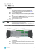
Section 2 The Retrofit Preparation Step 1: Use Sensor Configuration Editor and a SLTA if you wish to download and save the current Sensor configuration out of the racks for later reference. For information on this process contact ETC Technical Services (see page 1). Step 2: Turn off main power to the rack(s). Step 3: Remove the eight dimmer modules above the ECEM (if retrofitting an ESR36 or 48 rack, remove the eight modules below the ECEM as well).
through the standoffs on the side of the backplane into the rack metal Step 5: Pull backplane towards the front of the rack to free the backplane side tabs Step 6: Bend the right side of the backplane metal toward the centre (away from the side of the rack) Step 7: Slide backplane metal forward to remove it from the rack, cut the earth lead to the chassis and discard the wire. Step 8: Mark the connectors on the grey dimmer output ribbon cables (using permanent marker).
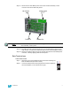
Step 17: Disconnect the three Molex power connectors and the small relay control connector from the fan filter relay board. Fan Output Power In Note: Control Input Power Out The fan filter relay board is not used after upgrade. It can be removed from the rack if desired, or left in place. Step 18: By pulling the relay control wires through, you should be able to remove them from the rack. You will be left with three beacon wires at the backplane location.
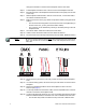
Transfer DMX Wires When transferring wire groups be sure to transfer all wire groups (except those designated as ETCLink) to the new connectors separately to avoid confusion. a: In most cases stranded wire has been used for the data terminations. If so, terminate the DMX wiring to the new connectors (found in the kit) in the same manner as they were to the old backplane. Double-up the DMXA pass-thru wiring to the same terminals as the DMXA wires.
Backplane Settings Upgrade kit backplanes ship from the factory with all DIP switches in the off (down) position. You will have to set the DIP switches on the new backplane to match your rack. You will also have to verify the termination switch settings. Set termination to “Off” (middle position) Emergency Contact (Panic) switch Set DIP switches a: Set both termination switches to “Off” (middle position) for all racks except the last rack in your system.
Terminating the ethernet cable inside the rack Since you will be adding ethernet capability to your ESR rack, ETC has provided the CAT5 Termination Kit (ETC Part#4101A2003). This kit includes a CAT5 connector and a small surface mount box (called a “Biscuit Box”) as well as an instruction sheet. Follow the instructions in this kit for terminating the ethernet cable at the CAT5 connector and enclosing the connector in the biscuit box.
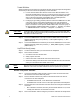
becomes stressed or pinched. Step 5: Insert the backplane tabs in the sides of the rack. Step 6: With the tabs fully inserted in the sides of the rack, pull the backplane towards the front of the rack to line up the screw holes in the upper side corners to line up. Step 7: Note: Screw with sleeve Single-height backplane shown. Install one screw with a sleeve in the upper-corner (for single-height backplanes) or the middle of the rear edge (for dual-height backplanes) of each side of the backplane.
Change out the Beacon PCB Step 1: Remove the top four dimmer modules from the rack to allow access to the PCB. Step 2: Remove the two screws that hold the beacon PCB in the face of the rack. Note: Be sure to use a properly sized screw driver (#2 Phillips) and a good amount of force as these screws are kept in place with thread locker.
Repeat the above steps for the remainder of connected racks. Note: Please return old ECEM processors, ECEM backplanes, and fan relays to the local ETC office (see page 1 for address). Verify the Retrofit Step 1: Put the dimmer modules back in the rack in the correct/original order. Step 2: Put the CEM3 in the rack. Step 3: Power up the rack. Step 4: Check that the CEM3 powers up and the rack fan turns on. (The only rack errors should be a lack of DMX on the ports if the DMX source is not present.
Corporate Headquarters 3031 Pleasant View Road, P.O.