® Sensor + Rack (ESR+ Series) CEM + to CEM3 Retrofit Manual Revision A C o p y r i g h t © 2 0 1 1 E le c tr o n i c T h e a t r e C o n t r o l s , I n c . All Rights reserved. P r o d u c t in f o r m a t i on a n d s p e c i f i c a t i o n s s u bj e c t t o c h a n g e .
E T C p e r m i t s t h e r e p r o d u c t i o n o f m a t e r i a l s i n t h i s m a n u a l o n l y f o r n o n - c o m m er c i a l p u r p o s e s . A ll o t h e r r ig h t s a r e r e s e r v e d b y E T C . ET C ®, a n d S e n s o r ® a r e r e g i s t e r e d t r ad e m a r k s o f E l e c t r o n i c T h e a t r e C o n tr o l s , I nc . i n t h e U n i t e d S t a t e s a n d o th e r c o u n t r i e s .
Introduction This manual is intended to guide ETC Service Technicians through the process of upgrading existing Sensor+ rack installations to Sensor3 racks with a CEM3 control module. This manual covers ESR+12, ESR+24, ESR+36 and ESR+48 permanent installation dimming racks. Contacting ETC Technical Services If you have questions about the retrofit process that are not answered in this manual, please contact ETC Technical Services at the appropriate office below.
Safety Please note the following safety warnings before use: • Disconnect power from the racks before all maintenance. WARNING: Dimmer racks without an accessible power disconnect device cannot be serviced safely. Before removing dimmer or control modules for service, deenergise main feed to dimmer rack and follow appropriate electrical safety procedures for your region. Overview of this Manual Reference this manual throughout the retrofit procedure.
Section 1 Unpack and Organise Parts/Components ETC Part Number Sensor Beacon Blue Assembly 7141B5109 Sensor3 Install Rack Door Label 7141A4001 CEM+ to CEM3 Backplane Power Adapter Harness 7144B7001 Sensor3 ESR Install Rack Backplane Assembly 7144A2000-CFG Sensor3 ESR Install Rack Backplane/NEFM Assembly 7144A2001-CFG Sensor3 ESR CEM+ to CEM3 Retrofit Manual 7144M2300 Screw 6-32 X 3/8 Ph PH MS CP W/Patch HW222 Screw 4-40x3/8 PhOHMS HW171 Screw 4-40x3/8 PhOHMS HW196 Cable tie 4" Hi-temp Black HW7121 CEM3 Bac
4 CEM3 Sensor+ ESR+ Rack Retrofit Manual
Section 2 The Retrofit Preparation Step 1: Use the Sensor+ Connect web interface to download and save the current configuration out of the rack for later reference. Instructions on saving your configuration from this interface can be found in any CEM+ Software Release Note or any CEM+ Configuration Manual available for download from the ETC website (www.etcconnect.com). Step 2: Turn off main power to the rack(s).
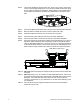
Step 3: Unscrew the backplane metal from the rack. There is one screw in each uppercorner on single height backplanes; one screw in the middle of each side, along the rear edge for dual height backplanes. Discard these screws. Replacement screws with thread locker are provided (ETC Part# HW377) and will be used later. 3 Remove the backplane screws 6 5 4 5 Single height backplane shown Step 4: Push the backplane towards the back of the rack to free the backplane side tabs.
IEC Componen t Transfer (IEC ONLY) You must transfer the components from the NEFM slot to the new backplane. a: Using a small blade screwdriver, press the locking tabs for the plastic cable grommet inward one-at-a-time and then push the grommet out of the old backplane. b: From the front face of the backplane, insert the cable grommet into the appropriate round hole in the new backplane and press until the tabs lock it in place.
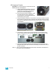
Attach New Power Harness Step 1: Connect the old power connector to the new power harness adapter found in the kit. The connectors are keyed - the power connectors only fit one way. New Power Harness Step 2: Run the green earth wire from the power harness adapter between the bus bar and the rack wall avoiding any interference with other wires in the rack. Step 3: Carefully route the earth wire around the rear interior of the rack to the earth bar.
wires to the new location. Carefully pull excess slack in the beacon wires down from the top of the rack. • Cut one or two of the bottommost wire ties that bundle the wires. This will free up more slack. • Prise one or more sticky backs off of their mounting locations to free up more slack.
. Step 5: Earth wire (IEC Only) connect the brown and blue wires to the rear of the IEC connector in the NEFM slot. Connections should be made according to the image at right. Connect blue wire here Connect brown wire here Step 6: Make the power and data connections on the backplane. a: Install the dimmer output ribbon cables. Open the black retaining tabs for each connector until they are at a 45° angle to the backplane.
Step 9: With the tabs fully inserted in the sides of the rack, pull the backplane towards the front of the rack to line up the screw holes in the upper side corners to line up. Screw with sleeve Step 10: Install one screw with a sleeve in Single height backplane shown the upper-corner (for singleheight backplanes) or the middle of the rear edge (for dual-height backplanes) of each side of the backplane.
Rack Model ESR3-36AFN ESR3-48 ESR3-48N ESR3-48AF ESR3-48 AFN 1 DIP switch Number 2 3 4 5 6 7 On On On On On On On On On On On On 8 “On” position = switch pushed to the top d: Check to see that the “Emergency Contact” switch is set to the appropriate position. • If your system has no panic circuit, the switch should be set to the middle position, “DISABLED”. • If your panic circuit includes a Normally Open contact closure, the switch should be set to the top position (NO).
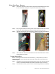
Change out the Beacon PCB Note: Although the colour of the beacon is unchanged, the voltage is different. The part number of the new PCB is printed on the circuit board (7141B5109). Step 1: Remove the top four dimmer modules from the rack to allow access to the PCB. Step 2: Remove the two screws that hold the beacon PCB in the face of the rack. Note: Be sure to use a properly sized screw driver (#2 Phillips) and a good amount of force as these screws are kept in place with a thread locker.
source is not present. Note: When first booting, CEM3 may upload firmware into the AF2 cards. This may take 10 minutes or more and is normal for a firmware update. Configure the CEM3 Step 1: Configure the rack to reflect the dimmer module types installed. Verify that the rack type is correct (CEM3 should have determined this from the DIP switch settings - see Backplane Settings, page 11). Configuration of the CEM3 is done using the front face panel interface.
2 The Retrofit 15
16 CEM3 Sensor+ ESR+ Rack Retrofit Manual
Corporate Headquarters 3031 Pleasant View Road, P.O.