® Sensor Rack (SR and HSR Series) CEM to CEM3 Retrofit Manual Revision A C o p y r i g h t © E le c tr o n i c T h e a t r e C o n t r o l s , I n c . All Rights reserved. P r o d u c t in f o r m a t i on a n d s p e c i f i c a t i o n s s u bj e c t t o c h a n g e .
E T C p e r m i t s t h e r e p r o d u c t i o n o f m a t e r i a l s i n t h i s m a n u a l o n l y f o r n o n - c o m m er c i a l p u r p o s e s . A ll o t h e r r ig h t s a r e r e s e r v e d b y E T C . ET C ®, a n d S e n s o r ® a r e r e g i s t e r e d t r ad e m a r k s o f E l e c t r o n i c T h e a t r e C o n tr o l s , I nc . i n t h e U n i t e d S t a t e s a n d o th e r c o u n t r i e s .
Introduction This manual is intended to guide ETC Service Technicians through the process of upgrading existing Sensor rack installations to Sensor3 racks with a CEM3 control module. This manual covers SR6, SR12, SR24 and SR48 as well as HSR model permanent installation dimming racks. Contacting ETC Technical Services If you have questions about the retrofit process that are not answered in this manual, please contact ETC Technical Services.
Safety Please note the following safety warnings before use: • Disconnect power from the racks before all maintenance. WARNING: Dimmer racks without an accessible power disconnect device cannot be serviced safely. Before removing dimmer or control modules for service, deenergize main feed to dimmer rack and follow appropriate Lockout/Tagout procedures as described in NFPA Standard 70E.
Section 1 Unpack and Organize Parts/Components ETC Part Number Beacon Door Acrylic 7051A4116 CAT5 Termination Kit 4101A2003 Sensor Beacon Blue Assembly 7141B5109 Sensor3 Install Rack Door Label 7141A4001 8-pin Screw Terminal Data Connector J3407-F CEM Classic to CEM3 Backplane Power Adapter Harness 7141B7010 Sensor3 Install Rack Backplane Assembly 7141A2003-CFG Sensor3 ESR/HSR Install Rack Backplane Assembly 7144A2000-CFG Sensor Rack CEM Classic to CEM3 Retrofit Manual 7141M2310 16 pin power transition PCB
Required Tools #1 Phillips screwdriver #2 Phillips screwdriver 1/4” flat head screwdriver Electrical tape Heat gun Diagonal wire cutter Permanent marker Wire strippers 4 CEM3 Sensor Rack Retrofit Manual
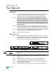
Section 2 The Retrofit Preparation Step 1: Use Sensor Configuration Editor and a SLTA if you wish to download and save the current Sensor configuration out of the racks for later reference. For information on this process contact ETC Technical Services (see page 1). Step 2: Turn off main power to the rack(s). Before removing dimmer or control modules for service, de-energize main feed to dimmer rack and follow appropriate Lockout/Tagout procedures as described in NFPA Standard 70E.
sliding it out of the notch in the rack and carefully pushing it through the backplane metal. This connector will be used in the upgrade. Step 7: Unscrew the backplane metal from the rack. (One screw in the upper corner of each side - two screws total.) Discard these screws. Replacement screws with thread locker are provided (ETC Part# HW377) for later use.
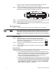
CAUTION: If using the IDC connector for CAT5 solid-core wiring, you must start with clean wire ends (clip the old punched end. Re-punching the old ends could result in an intermittent or failed connection. Step 5: Disconnect the DMXA wires from slots 1,2 and 3 of the J2 connector. Step 6: Connect the DMXA wires to an 8-pin connector. DMXA wires connect to the following terminals: Gray wire - 1, Black - 2, Red - 3. Step 7: Disconnect the DMXB wires from slots 9 and 10 of the J2 connector.
Step 4: Center the provided 4 1/2” x 1/2” dia. heat shrink tubing over the power harness connectors (leaving at least 1 1/4” past each connector). Be sure to keep the green ground wire for the new harness out of the heat shrink as you will need to run this ground to a different location. 4 1/2" Step 5: Contract the heat shrink using a heat gun. Step 6: Tuck the power harness connection bundle between the bus bar and the rack wall.
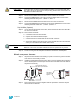
Step 2: Mate the transition cards with the ribbon cable edge connectors as indicated below. Secure the ribbon cable connectors to the transition cards with wire ties. The tie wrap binding needs to be on the top for an Upper board and on the bottom for a Lower board for clearance. Clip wire tie ends for neatness.
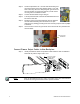
Install the New Backplane Step 1: Ensure the DMX termination switches are set properly. Termination should be turned on for the last physical rack in the DMX daisy-chain (No DMX wiring leaves the rack from that port). Step 2: Bend one arm of the new backplane metal in towards the opposite arm (about 30 deg). Step 3: Insert the backplane metal on an angle. Then straighten it once it is past the face of the rack.
Step 6: Insert the backplane tabs in the sides of the rack. Step 7: With the tabs fully inserted in the sides of the rack, pull the backplane towards the front of the rack to line up the screw holes in the upper side corners to line up. Step 8: Install one screw with a sleeve in the upper-corner of each side of the backplane. Note: Screw with sleeve You cannot use the old screws without the additional shoulder-sleeve as they will block the CEM3 from being fully inserted.
Change out the Beacon PCB Step 1: Remove the top four dimmer modules from the rack to allow access to the PCB. Step 2: Remove the two screws that hold the beacon PCB in the face of the rack. Note: Be sure to use a properly sized screw driver (#2 Phillips) and a good amount of force as these screws are kept in place with thread locker.
Verify the Retrofit Step 1: Put the dimmer modules back in the rack in the correct/original order. Step 2: Put the CEM3 in the rack. Step 3: Power up the rack. Before removing dimmer or control modules for service, de-energize main feed to dimmer rack and follow appropriate Lockout/ Tagout procedures as described in NFPA Standard 70E. It is important to note that electrical equipment such as dimmer racks can present an arc flash safety hazard if improperly serviced.
Corporate Headquarters 3031 Pleasant View Road, P.O.