Matrix II Rack Installation Manual RA (Rear Access) and SF (Swing Frame) version racks Revision A Co py ri gh t © 20 12 El ec t roni c Th ea tr e Co nt r ol s , Inc . Al l Ri gh ts res e rv e d. Pr od uc t i nf o rma ti o n an d s pe c i fi c ati ons s u bj ec t to c ha ng e .
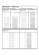
Matrix MkII Racks – standard range Rear Access Rack max capacity (160cm high) 7541A1714: 72 x 16A 7541A1716: 72 x 16A or, 7541A1715: 108 x 16A 60 x16A and12 x 32A 7541A1715: 54 x 32A Swing Frame Rack max capacity (200cm high, front access) 7542A1720: 108 x 16A 7542A1721: 162 x 16A 7542A1725: 81 x 32A Rear Access Rack max capacity (200cm high) 7541A1717: 108 x 16A 7541A1719: 108 x 16A or, 7541A1718: 162 x 16A 84 x16A and 24 x 32A 7541A1724: 81 x 32A 7542A1722: 108 x 16A or 84 x16A and 24 x 32A
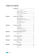
Table of Contents Introduction ........................................................... 1 How to use this guide .......................................................... 1 Warnings and Notice Conventions...................................... 1 Scope of this Guide ............................................................. 1 Module vs. Rack compatibility chart.................................... 2 Contacting ETC® ................................................................
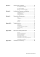
Section 7 Check Power Installation .................................... 16 Checking Main Power Wiring ............................................ 16 Checking Load Wiring ....................................................... 16 Optional – Checking Line Voltages .................................. 17 Section 8 Installing the Processor and Modules ................. 17 Installing the Processor ..................................................... 17 Identifying Modules .....................................
Introduction Welcome to the installation manual for Matrix® Mk.II dimmer racks. This manual contains the procedures for safe and efficient installation of Matrix Mk.II rear access racks and swing frame racks and includes information on electrical wiring installation and the complete dimming system checking. It does not include programming and commissioning as these subjects are described in the relevant ETC operational manuals. How To Use This Guide Use this guide during system installation.
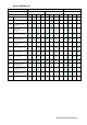
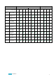
Module compatibility chart Rear access Rack version 1.6m Rack height 7542A-- Swing frame 2.0m 2.0m Channels (max) 72 108 72 54 108 162 108 81 108 162 108 81 Ref.
Rear access Rack version 1.6m Rack height Channels (max) Swing frame 2.0m 2.0m 72 108 72 54 108 162 108 81 108 162 108 81 1714 1715 1716 1723 1717 1718 1719 1724 1720 1721 1722 1725 7541A-- Ref.
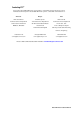
Contacting ETC® For questions about Matrix Mk.II rack system delivery, contact ETC Systems Group. For general information/technical questions about Matrix Mk.II rack systems, contact ETC Technical Services. Americas Europe Asia ETC International ETC Europe Ltd. ETC Asia Ltd.
Section 1 Preparing for Installation Unpack and Inspect Before starting the installation, check the shipment to confirm it arrived complete and undamaged. A Matrix II rack is shipped empty of modules in a transit box suitable for movement by a pallet truck. The modules and processor are separately packed in individual single-use transit boxes. Each rack has an identification label mounted inside the rear door with a serial number and CE mark.
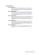
Local Requirements European Requirements Matrix II has been designed to European standards for electrical switchgear EN60439. It is CE marked. See Appendix C: Matrix II Declaration of Conformity. Ensure that all European electrical health and safety, and working directives are met when installing Matrix II. Power Supply Requirements Standard Matrix II racks are designed for operation with a single 3-phase star 380V – 415V RSTNE supply.
Dimmer Room Requirements Location o A clean (not dusty) temperature-controlled environment o Restricted public access to prevent any unauthorised tampering with the dimmer settings o Soundproofing or performance area separation to muffle ventilation fan noise. Please see Appendix B: Matrix Mk.II+ Rack Specifications, for environmental details.
Accessibility Allowing space around the rack (Rear access racks) o Rear access racks require adequate space in front to remove and replace modules (minimum 80cm, 150cm recommended) and rear access to allow the rear door for ventilation purposes and so that the door can be opened fully for installation and maintenance access (minimum 100cm, 180cm recommended). o Racks may be positioned with their side to a wall surface, and may be located side to side as required.
Section 2 Positioning of Racks Description (Rear Access racks) Rear access racks are available in 160cm or 200cm high versions and are available in 4 standard module configurations for each version. Both height versions are 60cm wide and 80cm deep. Each rack is supplied with two side covers. The supplied intermediate side panels may be discarded between racks.
Positioning Racks The racks are heavy, so it is advisable to prepare carefully before moving the racks into their final position to avoid having to reposition racks if something is not ready, or the racks are not positioned in the correct order.
Section 3 Installing Main Supply Cables WARNING: Ensure that it remains impossible to apply power to the main supply cable while installation of the main supply rack connections are being made. Ideally, connect the main supply cables to the dimmer racks before making connections to the supply switchgear. IT MUST NOT BE POSSIBLE TO ACCIDENTALLY APPLY POWER TO THE RACK DURING THIS INSTALLATION PROCESS.
Fuses The fuse protection employed in the rack provides a single 63A Siemens type D02 for each module position, and three 25A Siemens type D02 fuses for the processor. The module fuses limit the maximum current available to each module to 63A. The three processor fuses are located at the top row of the fuse panel on both the 1.6m and 2m high racks. In addition, each module incorporates a 15A 32mm A/S fuse per dimmer or switch power section.
Section 4 Installing Load Cables Terminations Terminals for the load wiring are located to the left of the rack at the rear and are accessible when the rear door is opened. The terminals for 3kW circuits are arranged in groups of three (L, N, E) corresponding to the number of channels in each row (3 modules) of the cabinet. Terminals for 5kW and 12kW circuits are located in pairs with the earth terminals located separately but adjacent to the L and N terminals.
Section 5 Installing Data Cables All Matrix II dimmer racks accept data in Ethernet and discrete DMX formats. All control connections are made at the rear of the processor module, on the data PCB that can be identified by the attached ribbon cable. There is one data PCB per rack. Use provided lance and forms as a tie off for DMX and Ethernet cables in the swing frame racks. Data PCB at the rear of the Matrix II Processor tray.
Section 6 Finishing Installation Visual inspection After the supply, load and data terminations are completed, the rack should be checked as follows: o Check all terminals and fuses have been tightened, especially the earth bonding points o Tidy all internal cables and add cable ties where needed o Remove excess or unwanted wiring o Fit the bus bar cover panel o Secure all removable panels o Remove all temporary protective covers Cleaning Before installing any electronics modules, ensure that th
Section 7 Check Power Installation Checking main power wiring WARNING: Power must be turned OFF when you perform this procedure. Check resistance between phases, neutral and earth busses.
Section 8 Installing the Processor and Modules CAUTION: Before unpacking and installing the electronic modules into the Matrix rack, ensure that all terminals have been correctly tightened, the rack is clean and any protective plastic has been removed. Identify the modules used in the system and separate the processor from the Matrix II modules. Locate the operator manuals from the processor and modules as these will be required during the installation process.
Installing the modules WARNING: Do not force any module into a connector if resistance is felt. This could mean that the wrong module is being inserted into the slot, or that the connector has a damaged pin. CAUTION: SWING FRAME RACK Before installing any modules, close the swing frame and lock it. Step 1: Locate the correct module for each slot and check that the MCBs / RCBOs on the front panel are switched off. Note that any blank spaces in the rack should be fitted with ‘airflow’ modules.
Section 9 Preventative Maintenance ETC Matrix II dimming systems are designed for long and reliable service, but will benefit from annual checks of parts of the system. This section outlines the sort of checks which should be part of any regular maintenance regime.
Appendix A Troubleshooting Power loss Total power failure If all power to the rack fails (if it is not already obvious, the processor’s three phase indicators will be off when there is a total power loss) initially check if the main supply breaker has tripped. If not, check if there is any other equipment supplied from the same source and whether or not that is working correctly.
To check module power and data WARNING: The Matrix rack has inherent safety from electrical shock if a module is removed with power on. However, the following checks on the rack socket connections should only be attempted by a qualified technician, It is possible to access the module sock from the front of the rack to aid fault finding.
Multipin socket for 4 x 5kW module (Custom 32A and standard 63A/12kW modules) Multipin socket showing the position of the standoff pillar (arrowed) and pin numbering. Mod. A Note that Mod A and Mod B are paralleled. Pin 1 2 3 4 5 6 7 8 Mod. B 1 2 3 4 5 6 7 8 Connection Ch 1 - L Ch 2 - L Ch 3 - L Ch 4 - L Ch 1 - N Ch 2 - N Ch 3 - N Ch 4 - N Ch 1 - L Ch 2 - L Ch 3 - L Ch 4 - L Ch 1 - N Ch 2 - N Ch 3 - N Ch 4 - N Fan not working With Matrix II, the ventilation fans are located in each module.
Appendix B Matrix Mk.II Rack Specifications General Racks are available in nine configurations: 1.6m high Rear Access (RA) racks [160cm x 60cm x 80cm 170kg (excluding modules)] o 72ch 18 modules 4x16A [7541A1714] o 108ch 18 modules 6x16A [7541A1715] o 72ch 15 modules 4x16A, 3 modules 4x32A* [7541A1716] 2.
Part numbers – main product items Racks 7541A1714 1.6m RA Rear Access Rack, 72ch 18 modules 4x16A 7541A1715 1.6m RA Rear Access Rack, 108ch 18 modules 6x16A 7541A1716 1.6m RA Rear Access Rack, 72ch 15 modules 4x16A, 3 modules 4x32A 7541A1717 2.0m RA Rear Access Rack, 108ch 27 modules 4x16A 7541A1718 2.0m RA Rear Access Rack, 162ch 27 modules 6x16A 7541A1719 2.0m RA Rear Access Rack, 108ch 21 modules 3x16A, 6 modules 4x32A 7542A1720 2.0m SF Swing Frame Rack, 108ch 27 modules 4x16A 7542A1721 2.
Part numbers – factory configured option kits Note: Factory option kits below are available to change the output wiring. This modification can only be undertaken by qualified ETC staff or ASC technicians.
Appendix C Conformity Certificates Matrix Mk.
Corporate Headquarters 3031 Pleasant View Road, P.O.