Architectural Control Processor Configuration Manual 1.0 C o p y r i g h t © E le c tr o n i c T h e a t r e C o n t r o l s , I n c . All Rights reserved. P r o d u c t in f o r m a t i on a n d s p e c i f i c a t i o n s s u bj e c t t o c h a n g e . P a r t N u m b e r : 7186M1200-1.0.
ET C ®, U n i s o n ®, a n d E c h o ™ , a r e e i t h e r r e g i s te r e d t r a d e m a r k s o r t ra d e m a r k s o f E l e c t r o ni c T h e a t r e C o nt r o l s , In c . i n th e U n i t e d S ta t e s a n d o t h e r c o u n t r i e s . A l l o t h e r t r a d em a r k s , b o t h m a r k e d a n d n o t m a r k e d , a r e th e p r o p e r t y o f t h e i r r e s p e c t i v e o w n e r s .
Table of Contents Introduction . . . . . . . . . . . . . . . . . . . . . . . . . . 1 Warnings and Notice Conventions . . . . . . . . . . . . . . . . . . . . . . .2 Contacting ETC . . . . . . . . . . . . . . . . . . . . . . . . . . . . . . . . . . . . . .3 Overview . . . . . . . . . . . . . . . . . . . . . . . . . . . . . . . . . . . . . . . . . . . . . .4 Concepts and Definitions. . . . . . . . . . . . . . . . . . . . . . . . . . . . . . .4 Installation Environment Requirements . . . . . . . . . . . . . . .
Emergency Setup . . . . . . . . . . . . . . . . . . . . . . . . . . . . . . . . . . .31 Quick Rack Setup . . . . . . . . . . . . . . . . . . . . . . . . . . . . . . . . . . .34 Arch Setup Menu . . . . . . . . . . . . . . . . . . . . . . . . . . . . . . . . . . . . . . .37 Remote Record . . . . . . . . . . . . . . . . . . . . . . . . . . . . . . . . . . . . .37 Data Source Settings. . . . . . . . . . . . . . . . . . . . . . . . . . . . . . . . .37 Data Loss & Power On . . . . . . . . . . . . . . . . . . . .
System. . . . . . . . . . . . . . . . . . . . . . . . . . . . . . . . . . . . . . . . . . . .74 Dimmers . . . . . . . . . . . . . . . . . . . . . . . . . . . . . . . . . . . . . . . . . .75 Set Levels . . . . . . . . . . . . . . . . . . . . . . . . . . . . . . . . . . . . . . . . .75 Presets. . . . . . . . . . . . . . . . . . . . . . . . . . . . . . . . . . . . . . . . . . . .75 Sequences. . . . . . . . . . . . . . . . . . . . . . . . . . . . . . . . . . . . . . . . .76 Files . . . . . . . . . . . . . . . .
Introduction Welcome to the Echo Architectural Control Processor (E-ACP) Configuration Manual. This manual contains information for user configuration and programming of the Echo ACP. The Echo ACP installs into a Unison DRd enclosure and provides centralized access to the dimming, switching, rack enclosure settings, DMX setup, and interface to Echo controls stations over the EchoConnect control network.
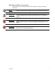
Warnings and Notice Conventions These symbols are used throughout this manual to alert you to danger or important information: Note: Notes are helpful hints and information that are supplemental to the main text. CAUTION: A Caution statement indicates situations where there may be undefined or unwanted consequences of an action, potential for data loss, or an equipment problem.
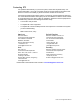
Contacting ETC For questions about delivery of your Echo system, contact ETC Systems Group. For general information, your most convenient resources are the references provided in this manual. To search more widely try the ETC web site at www.etcconnect.com. For technical questions about Echo systems, contact ETC Technical Services directly at one of the offices listed below. Emergency service is available from all ETC offices outside of normal business hours.
Overview Concepts and Definitions The Echo Architectural Control Processor (E-ACP) is just one component of the Echo system. The Echo ACP integrates the DRd rack with other Echo networked products (up to 15 other host products such as Sensor 3, Echo Relay Panel, other Echo ACPs) over the EchoConnect network and supports Echo Inspire stations (up to 16) when station power is supplied.
When configuring your DRd, using the Dimmer Setup menu, you must assign each dimmer to a Space. Spaces Spaces are logical divisions within a system that isolates station control (preset and sequence control) to the defined group of controllable outputs in that division. A single Echo ACP is limited to 8 spaces, and an Echo system supports up to 16 spaces. Each space must be configured using the Space Setup option in the Arch Setup menu.
Rack and System Feedback The Echo ACP provides feedback through the status indicators on the front panel of the Echo ACP. Each indicator is visible from the front panel of the Echo ACP with the DRd enclosure door closed. Additional status information is provided on the front panel of the Echo ACP display. Additional status information is provided on the front panel of the Echo ACP display. • By default, the “Dimming Rack Status” displays.
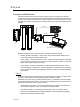
Right I/O The Right I/O board on the DRd enclosures provide a majority of the control inputs into the system including: DRd right I/O • EchoConnect Station Bus - station communication bus from the Echo ACP to the Echo control stations and other products. • DMX (Digital Multiplex) - addresses up to 512 channels of control. The Echo ACP supports one universe of DMX input. DMX through connections are available for use as needed. The DMXB connector is not used.
Installation Environment Requirements The Echo ACP is designed for use in a Unison DRd enclosure. The environmental conditions for the Echo ACP should adhere to the requirements set for the DRd enclosure. Reference the Unison DRd Rack Enclosure Installation Manual for complete details. • A clean (not dusty) temperature-controlled environment with an ambient temperature of 32-104°F / 0-40°C and ambient humidity of 10-90%, non-condensing. • Restricted public access to prevent tampering.
9 Echo ACP Configuration Manual
Chapter 1 UI Overview and Installation This chapter contains the following sections: 1 • User Interface Overview . . . . . . . . . . . . . . . . . . . . . . . . . . . . .11 • Install the Echo ACP . . . . . . . . . . . . . . . . . . . . . . . . . . . . . . . .
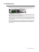
User Interface Overview The Echo ACP features a dynamic user interface with a touch wheel for easy menu navigation, an numeric button pad for direct selection, and a bright, easy to read graphic LCD. Additionally, an SD media card slot and integrated USB port for flash drive. LCD Display The Echo ACP features a backlit LCD capable of displaying 8 rows of text with 21 characters per line. The first row is reserved for the menu title.
Enter The enter button ( ) is used to commit an edit or an action such as to make a selection from the menu list or to commit a selected value. When focus is on the first text value (“Module Type:” in the example below) and an edit or change to the selection is desired, press enter ( ). The display changes to select the Module Type. Scroll to select the type and press enter ( ) to make the selection and return to the Dimmer Setup menu. Scroll again to change focus to the next selectable parameter for edit.
menu. Recent command navigation relies on the current user access level to display only accessible options. • Alternatively, while navigating certain menu items such as “Dimming Setup” or “Dimming Control” menus and selecting specific dimmers, use the [and] button to select dimmers out of sequence. For example, [1] [and] [5] [and] [8] ( ), selects dimmers 1, 5, and 8. Once selected you may use the numeric button pad to add a value to the selected dimmers or use the touch wheel to scroll to a desired value.
R e m ov a b l e M e d i a US B Port The Echo ACP includes a USB port for use with a flash drive, located on the front panel. The USB flash drive is not included and can be purchased separately. A USB flash drive can be used to store and load backup files of your architectural and dimming configurations. SD Media The Echo ACP includes a Secure Digital (SD) media card slot located on the front panel. The SD media card is not included and can be purchased separately.
Install the Echo ACP The Echo ACP is designed to slide in the bottom module slot of a Unison DRd enclosure. All data terminations used with the Echo ACP are terminated to the left and right I/O boards in the DRd enclosure. Install the Echo ACP only after the DRd enclosure has been installed and all wires have been terminated properly. WARNING: Rack enclosures installed without an accessible power disconnect device cannot be serviced or operated safely. Follow all local codes and restrictions.
System Status When the Echo ACP is installed and power is applied to the enclosure, the graphic LCD illuminates and displays Dimming Rack Status. Dimming Rack Status System OK DMX Start = 155 Ø1: 119 Ø2: 119 Ø3: 120 60Hz 102F v5.6.7 • • Clockwise rotation on the touch wheel changes the status display to Arch Control Status. Counter-clockwise rotation on the touch wheel changes the status display back to Dimming Rack Status.
17 Echo ACP Configuration Manuall
Chapter 2 Echo ACP Basic Navigation This chapter contains the following sections: 2 • Status Display . . . . . . . . . . . . . . . . . . . . . . . . . . . . . . . . . . . . .19 • Status / Error Messages . . . . . . . . . . . . . . . . . . . . . . . . . . . . .21 • Menu Navigation . . . . . . . . . . . . . . . . . . . . . . . . . . . . . . . . . . .
Status Di splay The Echo Architectural Control Processor (E-ACP) provides all of the basic rack and system information on the status display. When the Echo ACP is installed in a DRd enclosure, the dimming rack status display is the default status display. The architectural control status display is the only status display available when the Echo ACP is installed in an ERn enclosure. DRd Dimming Rack Status Display Dimming Rack Status System OK DMX Start = 155 Ø1: 119 Ø2: 119 Ø3: 120 60Hz 102F v5.6.
• internal operating temperature - The internal operating temperature is measured and displays on the dimming rack status display. By default, temperature is displayed in °F when the rack is 120, 240, or 277V AC, and in °C when the rack is 230 V AC. • rack software version - The rack software is specific to the dimming engine and may differ from the ACP software version.
Status / Error Messages Status messages display on both the dimming rack status display and the Arch Control Status display. When the Echo ACP is installed in a DRd enclosure, use the touch wheel to scroll clockwise ( ) to view the Arch Control Status display. Status messages provide you with system wide, rack specific or even just dimmer specific information including errors. Important errors may suppress display of other existing errors on the status display.
Status / Errors Messages Generated by the DRd Dimming Engine Message Displayed Description Action Rack Error / Rack Overtemp Ambient temperature is above rated temperature range. All dimmers in the enclosure are disabled from use until the ambient temperature is within an acceptable operating range. Rack Warning / High Operating Temp Ambient temperature is approaching maximum temperature. Correct the ambient temperature to within specification.
Menu Navigation The Echo ACP menu is designed with consistent navigation from the user interface either using the numeric button pad or the touch wheel. Note: To navigate the menu using the numeric button pad, press the #nav/thru button on the button pad. This enables number navigation and displays the specified numbers to the left of an existing menu list. See “#Nav/Thru” on page 13. The main menu is the root for all menu navigation.
Chapter 3 Programming This chapter contains the following sections: 3 Programming • About Menu . . . . . . . . . . . . . . . . . . . . . . . . . . . . . . . . . . . . . . .25 • Dimming Setup Menu . . . . . . . . . . . . . . . . . . . . . . . . . . . . . . .27 • Arch Setup Menu . . . . . . . . . . . . . . . . . . . . . . . . . . . . . . . . . . .37 • Dimming Control Menu . . . . . . . . . . . . . . . . . . . . . . . . . . . . . .43 • Arch Control Menu. . . . . . . . . . . . . . . . . . . . . . .
About Menu The “About” menu provides you direct access to view details about your dimmers, current level summary data, software version information, and information about which spaces in your Echo ACP configuration have combined control. Note: About 1 2 3 4 About Dimmer Levels Summary Version Info Space Combine The “About” menu is provided for you to view information only. There are no editing tools or menu lists available.
Version Info The “Version Info” menu displays the current full software version numbers, including build numbers, for each software type installed in the rack. Version Info Echo ACP App: 12.34.0.0.0.0.05 DRd: 2.1.0.0.0.0.4 FLO: 1.0.0.0.0.0.6 DALI: 1.0.0.0.0.0.7 Echo Protocol: 12.3.5.7.1.1.1 Echo PHY: 12.3.5.7.1.2.1 FLO and DALI options only appear if they are presently installed in the host DRd rack. Each DRd may have only 1 option installed, except when the rack type is the DRd12AX12X.
Dimming Setup Menu The “Dimming Setup” menu provides a range of options to setup a host DRd enclosure. Use the “Dimming Setup” menu to specify dimmer module types, customize dimmer properties, patch the rack dimmers to the specified DMX input and sACN input addresses, and setup emergency operation for the dimmers in the rack configuration.
Note: Each module type has a default set of properties such as the firing mode, dimmer curve, etc. When changing a module type, all dimmer properties for the specified dimmer(s) also change to match the new module type property defaults. You may edit the dimmer properties individually. Refer to Dimmer Module Defaults, page 65 for a listing of standard dimmer properties.
Patch DMX Input Patch DMX Input DIM DMX 1: 2: 3: 4: 5: 6: 111 112 NA 113 114 116 a a 111 b 368 b H a 115 L 117 b The Echo ACP supports one universe of DMX input patch. A universe is a group of 512 contiguous control channels. When using the “Patch DMX Input” menu, addresses may start at one or any number up to 512 minus the number of dimmers in the enclosure, depending on the type of enclosure(s) you are programming. The highest DMX address for any dimmer allowed is 512.
Patch Dimmers You may use “and thru” functions to specify a selection or range of dimmers for patch editing. Once your selection is made, press enter ( ) to accept the selection and begin editing. To remove the last selected dimmer from the selection, press the back button ( ). Continue pressing the back button ( ) to clear all undesired dimmers from the selection. Step 1: Make a selection of dimmers for patching using either the touch wheel or the numeric button pad.
A universe is a group of 512 contiguous addresses. When using the “Patch sACN Input” menu, addresses may start at one or any number up to 512 minus the number of dimmers in the enclosure, depending on the type of enclosure(s) you are programming. Patch sACN Input You may use “and thru” functions to specify a selection or range of dimmers for sACN patch editing. Once your selection is made, press enter ( ) to accept the selection and begin editing.
“Emergency Dimmers” displays for dimmer assignment. Assign dimmers to be “On” when the panic input is active and On 2: On 3: -assign other dimmers to turn off (also known as load-shedding). Emergency Dimmers 1: 4: On 7: On 10: -13: N A 15 B:O n 5: -8: On 11: O n 14: N A 16 A:O n 6: 9: 12: 15 A: 16 B: -On On On On Settings include: • “On” which is the default and indicates the dimmer will turn on to the emergency preset level when the emergency input is active.
Load Shedding Emergency Setup Emergency Dimmers Emergency Level: 100 Load Shedding: On Input Type: Maintained Active when: Closed When the DRd enclosure senses the loss of normal power, it bypasses the Echo ACP and drives selected emergency load circuits to the emergency level.
Quick Rack Setup Quick Rack Setup Voltage L-N Auto Rack Type: Auto Module Type: D20 Straight Balance: DMX Start Addr: 1 sACN Universe: 1 sACN Start Addr: 1 Apply Changes* Only Quick Rack Setup DMX Start Addr: sACN Universe: sACN Start Addr: Space: Temp: 1 1 1 1 Auto Apply Changes* Only Apply All The “Quick Rack Setup” menu provides you with easy access to set or edit the most important dimmer rack properties.
Module Type Module type allows you to quickly set all dimmers in the DRd rack to a single type. Available modules are determined by the voltage which is automatically determined at power up. Reference Dimmer Specifications, page 62 for dimmer module property defaults. • For a 100-130 V AC dimmer rack, the default is a D20 dimmer module. • For a 230-240V AC dimmer rack, the default is an ED15 dimmer module. • For a 277V AC dimmer rack, the default is an AD20 dimmer module.
sACN Universe This setting is automatically defaulted to sACN Universe “1”. sACN Universe corresponds to the input universe of control that the Echo ACP will receive control input from. The valid range is 1 - 63999. Step 1: Use the touch wheel to scroll to “sACN Universe” and press enter ( ) to select. Step 2: Use the touch wheel to scroll or use the numeric button pad to specify sACN universe. Press enter ( ) to select.
Arch Setup Menu Arch Setup Remote Record: Data Source Settings Data Loss & Power On Preferences Space Setup Network Settings Off The “Arch Setup” menu items governs how this controller uses available control sources. When configuring more than one Echo controller on the network, these settings must be set to each controller individually. R e m ot e R e c o r d Enable or disable remote recording of presets from controls on the EchoConnect station communication bus in this menu.
Arch Priority Set the priority level for Arch controls including the Echo ACP user interface, presets and sequence controls, and stations on the EchoConnect network. Step 1: Use the touch wheel to scroll to “Arch Priority” and press enter ( selection changes to the currently selected setting. ). The Step 2: Use the touch wheel, scroll to change the selection to any value between 1 and 201, with 201 being the highest priority. Press enter ( ) to select. The selection changes back to “Arch Priority”.
Power On Behavior Power On Behavior may be set to “None”, or configured to execute an action, such as playing a specific preset or a sequence. Step 1: Use the touch wheel to scroll to “Data Loss & Power On” from within the “Arch Setup” menu and press enter ( ). The DMX Loss Behavior, ACN Loss Behavior, and Power On Behavior menu lists display. Notice the three settings are separated vertically on the screen. You cannot select the heading, only the “Mode” and options from within.
B a c k li g h t The backlight setting specifies the performance of the user interface backlight. When the backlight setting is set to “Auto”, the inactivity timer is also the backlight timer. If the inactivity timer is set to “Never”, the backlight will time out after one minute. Backlight settings include: • “Auto” (LCD dims when the inactivity timer has expired) • “On (the backlight is always on) • “Off” (the backlight is always off).
Note: When exiting the Space Setup display and a space has been changed, and it had circuits assigned to it, a warning dialog displays for confirmation. WARNING Some Circuit numbers were edited by Space edits. Go to Dimmer Setup? Yes No Select “Yes” to be redirected to the Dimmer Setup menu, or press “No” to cancel and return to the previous selection. Use the touch wheel to scroll to and setup the next space or press back ( “Arch Setup” menu.
When “Automatic is selected: Scroll to “Apply and Exit”, then press enter ( Settings menu. Note: ). The display returns to the Network When “Automatic” is the selected IP Addressing mode, the IP Address, Gateway and Subnet Mask fields do not display. To identify the current IP Address, reference the Arch Control Status Display. When “Manual” is selected: Press enter ( ) to manually select each of the IP Address settings. By default, the manual IP settings for the Echo ACP are: IP Address 10.101.166.
Dimming Control Menu The “Dimming Control” menu is provided to set dimmer levels, check dimmers and release any set dimmer levels. Direct access to the “Dimming Control” menu is also selectable from the Control Menu Shortcut ( ) button. Dimming Control Set Levels Dimmer Check Release Set Levels Set Levels Set Levels 1 4 7 10 13 16 19 55 -50 50 NA --- 2 5 8 11 14 17 20 -50 FL 25 NA FL 50 3 6 9 12 15 18 21 FL --FL FL 75 50 All configured dimmers (up to 48) are displayed in the “Set Levels” menu list.
Dimmer Check Scroll to “Next Dimmer” and press enter to step through the dimmer list. Dimmer Check Dimmer Number Level Next Dimmer Previous Dimmer Scroll to “Previous Dimmer” and press to step back through the dimmer list. 1 80 current dimmer in check Level the dimmer will illuminate to (can be set to any value 0 - 100). The “Dimmer Check” menu provides a quick and easy method to step through all your individual dimmers. This is useful for checking lamps or checking focus.
Arch Control Menu The “Arch Control” menu provides access to architectural control objects such as presets and sequences. Arch Control Presets Sequences Presets Presets Space 1 Preset 15 Active Preset #: 12 Activate Record Fade Time: 0 min 2 sec The “Presets” menu provides the tools to edit the assigned Space, display preset status, activate, deactivate, record, and configure fade timing for the 64 built-in presets. The lowest configured Space displays by default.
Step 1: Scroll to “Activate” or “Deactivate” and press enter ( selected Preset state. ) to change the currently • Selecting to “Activate” a Preset in a Space automatically deactivates any other Preset that is currently active in the Space. Only one Preset can be active at a time in each Space. • Selecting to “Deactivate” a Preset in a Space deactivates the currently selected Preset in the selected Space.
Start / Stop Sequence When the Sequence is NOT currently playing, “Start” displays for selection on the following line. When the Sequence is playing, “Stop” displays for selection on the following line. Step 1: Scroll to “Start” or “Stop” and press enter ( ) to change the Sequence state. Sequence Mode Sequence Mode determines how the Sequence will behave when it is running. Options include “Bounce”, “Single” or “Loop”.
3 Step 5: Scroll to “Record” and press enter ( ). The current state of the output levels are recorded into the currently selected Step with the set Fade and Hold times. Step 6: Scroll to “Insert Step After” and press enter ( ). A new Step will be added into the Sequence directly after the currently selected Step. Up to 6 steps are allowed per Sequence, therefore when 6 Steps are created. The “Insert Step After” menu option will no longer be available for selection.
File Operations Menu File Operations Save Rack Configs Save Dimming Config Load Dimming Config Save Arch Config Load Arch Config Restore Defaults Update Firmware The “File Operations” menu provides you with the tools to save and load your Echo ACP and dimming configurations, restore system default properties and update firmware. Operations from this menu, with the exception of “Restore Defaults”, provide operations for saving and loading of files using SD media and USB flash drive removable media types.
Save Dimming Configuration The “Save Dimming Config” operation only saves the dimming configuration file to the root directory of the removable media. File Operations Save Dimming Config Save Rack Configs Save Dimming Config Load Dimming Config Save Arch Config Load Arch Config Restore Defaults Update Firmware Name: Save to USB Media Save to SD Media Step 1: Install the removable media into the correct slot on the front of the ACP.
Load Dimming Configuration File Operations Load Dimming Config Save Rack Configs Save Dimming Config Load Dimming Config Save Arch Config Load Arch Config Restore Defaults Update Firmware Load from USB Media Load from SD Media Load Dimming Config SD:\folder <...> DRd6_1 DRd12_2 DRd12_3 DRd6_4 The “Load Dimming Configuration” operation provides you with tools to load an existing rack configuration from a removable media device into the Echo ACP and DRd dimming electronics.
Save Arch Configuration The “Save Arch Config” process saves only the architectural configuration to the root directory of the removable media device.
Load Architectural Configuration The “Load Arch Config” menu provides you with tools to load an existing Echo architectural configuration from a removable media device, such as an SD media card or USB flash drive. Loading a new architectural configuration file overwrites any previous architectural configuration on the Echo ACP.
Restore Defaults The “Restore Defaults” operation erases all memories, excluding removable media, and returns the specified configuration(s) to factory defaults. “Restore Defaults” is prohibited while the Emergency input is active. Note: Before proceeding with “Restore Defaults”, save your current architectural and dimming rack configurations to removable media device so that you can always revert back if needed.
Update Firmware Firmware is the embedded software for the Echo Architectural Control Processor, dimming engine, DALI and fluorescent option boards. Echo ACP firmware is available from Electronic Theatre Controls, Inc. and should be saved to the root directory of your removable media for loading on the Echo ACP. CAUTION: Use caution when updating Echo ACP firmware.
Vi ew/Clear Errors Menu The “View/Clear Errors” menu list displays current system errors in the order of severity, with the most severe error first in the list. When duplicated or new errors are detected, they replace any previous errors of the same type in the list. Note: View / Clear Errors Dimmer Errors Overtemp: Dim 13 Rack Communication Failure! DMX input Inactive Reference Status / Error Messages, page 21, for a list of most common errors and the resulting actions.
Restri cted Access Menu The “Restricted Access” menu provides two levels of user access to the Echo ACP menu, “User” and “Admin” and can be set to always require a user login. Step 1: Scroll to select “Restricted Access” and press enter ( ). The “Restricted Access” menu list displays according to the current user access level.
Change Passcode Change Admin Passcode New Passcode: Verify New: Accept Changes **** **** The process identified below is identical for changing both the “Admin” and the “User” passcode. When logged in with “Admin” level access, you are provided with the ability to change both the admin passcode and the user passcode. When logged in with “User” level access, you are provided only with the ability to change the user passcode.
59 Echo ACP Configuration Manual
Chapter 4 Service 4 Service • Service and Maintenance . . . . . . . . . . . . . . . . . . . . . . . . . . . .61 • Hardware Reset Switch . . . . . . . . . . . . . . . . . . . . . . . . . . . . . .
Service and Maintenance Replace a Echo ACP Step 1: Open enclosure door. Step 2: If possible, save all configuration files to removable media. See “Save Arch Configuration” on page 52. When the Echo ACP is hosted by a Unison DRd rack, the Save Rack Configurations action also saves the dimming rack configuration with the architectural configuration. Step 3: Remove the existing Echo ACP from the rack. a: Hold both sides of the Echo ACP and pull straight out.
Appendix A Dimmer Specifications Unison DRd Rack Compatibl e Modules 120V AC Dimmer Modules Module Type AFM CC15 CC20 D15 D15E D15F D15FB D20 D20E D20F D20FB ELV10 R15 R20 L10 L10F Description Air Flow Module Dual 15A Constant Circuit Breaker Module Dual 20A Constant Circuit Breaker Module Dual 15A, 1.8KW, 350µS Dimmer Module Dual 15A, 1.8KW, 500µS Dimmer Module Single 15A, Fluorescent Dimmer Module Single 15A, Fluorescent / Battery Dimmer Module Dual 20A, 2.4KW, 350µS Dimmer Module Dual 20A, 2.
230V AC Dimmer Modules (Continued) Module Type Description Part Number ED25RS ED25RE ER6 ER10 Dual 6A, 1.3KW 400µS Neutral Disconnect Dimmer Module Dual 6A, 1.3KW, 400µS Dimmer Module Dual 10A, 2.3KW 400µS Dimmer Module Dual 10A, 2.3KW, 400µS Dimmer Module Dual 10A, 2.3KW 400µS Neutral Disconnect Dimmer Module Dual 10A, 2.
277V AC Dimmer Modules Module Type AFM ACC15 ACC20 AD15 AD15F AD15FB AD20 AD20F AD20FB AL5 AL5F AELV5 AR15 AR20 A Material description Air Flow Module Dual 15A at 277V AC, Constant Circuit Breaker Module Dual 20A at 277V AC, Constant Circuit Breaker Module Dual 15A, 4.1KW at 277V AC, Dimmer Module Single 15A, 4.1KW at 277V AC, Dimmer Module Single 15A, Fluorescent / Battery Dimmer Module Dual 20A, 5.5KW at 277V AC, Dimmer Module Single 20A, 5.
Dimmer Module Defaults 120V AC Default Mode Default Curve 230/ 240V AC Default Mode Default Curve 277V AC Default Mode Default Curve AFM Off Linear AFM Off Linear AFM Off Linear CC15 Off Linear ECC15 Off Linear ACC15 Off Linear CC20 Off Linear ECC25 Off Linear ACC20 Off Linear D15 Normal Mod-Sq *ED15 Normal Mod-Sq AD15 Normal Mod-Sq D15E Normal Mod-Sq ED15N Normal Mod-Sq AD15F 2/3 wire Fluorescent Linear D15F 2/3 wire Linear Fluorescent ED15E Normal
Compati ble Loads 100 - 120V AC Racks Module Type AFM CC15 and CC20 D15 and D20 D15E and D20E D15F and D20F D15FB and D20FB ELV10 L10 L10F R15 and R20 Description of Purpose required in empty dimmer slots direct connection from line lug to load lugs protected by 15 or 20 amp circuit breaker Compatible Loads not applicable constant loads such as power supplies or other constant-on loads Incandescent, 2 and 4 wire standard 15 or 20 amp dimmer fluorescent, magnetic low voltage, enhanced dimmer with 500s ris
230 and 240V AC Racks (Continued) Module Type HELV5 HR15 HD15F Description Compatible Loads 240V AC 5 amp reverse phase module electronic low voltage loads 240V AC 15 amp, level activated mechanical any switched load relay 3 wire dimmable electronic 240V AC 15 amp fluorescent dimmer module fluorescent ballast 277V AC Racks Module Type AFM Compatible Loads not applicable constant loads such as power ACC15 and ACC20 supplies or other constant-on loads Incandescent, 2 and 4 wire standard 15 or 20 amp dimmer
Dimmer Modes Normal Mode Property Units Curve Voltage Regulation Dynamic Preheat Min Scale Max Scale Transformer Mode Threshold Default 230/240V Default 120V not applicable On / Off Seconds / Off Volts Volts On/Off % Control Mod-Square On Off 6V 118V Off 1% (>0%) Mod-Square On Off 12V 230V Off 1% (>0%) Default 277V Mod-Square On Off 14V 277V Off 1% (>0%) “Normal Mode” typically applies to standard dimmer modules.
2 and 3 Wire Fluorescent Mode Property Curve Voltage Regulation Dynamic Preheat Min Scale Max Scale Transformer Mode Threshold Units not applicable On / Off Seconds / Off Volts Volts On / Off Control Default 120V Linear On Off 56V 120V On 1% (>0%) Default 230V Linear On Off 108V 230V On 1% (>0%) Default 277V Linear On Off 130V 277V On 1% (>0%) 4 Wire Fluorescent Mode Property Curve Voltage Regulation Dynamic Preheat Min Scale Max Scale Transformer Mode Threshold Units not applicable On / Off Seconds /
Off Mode Property Curve Voltage Regulation Dynamic Preheat Min Scale Max Scale Transformer Mode Threshold Units not applicable On / Off Seconds / Off Volts Volts On / Off Control Default 120V Linear Off Off 0 120V Off 0 Default 230V Linear Off Off 0 240V Off 0 Default 277V Linear Off Off 0 277V Off 0 Reverse Phase Mode Property Curve Voltage Regulation Dynamic Preheat Min Scale Max Scale Transformer Mode Threshold Note: Units not applicable On / Off Seconds / Off Volts Volts On / Off % Control Defau
Dimmer Properties Mode: The firing mode menu allows you to set a dimmer or a range of dimmers to a specific firing mode. Available firing modes include: • Normal: used for standard dimming of non-specialized load types. The dimmer operates with a modified square curve by default. • Dimmer Doubled: dimmer operates as two controllable circuits with two channels of control. This mode is displayed for use only with 120V AC / 60Hz systems utilizing ETC Dimmer Doubling™.
Minimum Scale: Minimum scale allows you to set a dimmer or a range of dimmers to a minimum output voltage, which is the bottom of the scaled output of the dimmer(s). The dimmer will switch on to an RMS output voltage of minimum scale voltage when the control level reaches the value set for threshold.
73 Echo ACP Configuration Manual
Appendix B Echo ACP Web Interface The Echo ACP features a web interface that is accessible over the system network using any internet browser (such as Internet Explorer®, Firefox™, Safari®, or Chrome®). This interface allows you to view the system status, perform basic panel functions, update firmware, and upload or download the rack configuration.
• DRd rack information which is visible from the front panel of the Echo ACP on the DRd Dimming Rack Status Display • Currently active errors that may exist in the system which are also visible from the DRd Dimming Rack Status Display and Arch Control Status Display. See also Status / Error Messages Generated by the Echo ACP and Status / Errors Messages Generated by the DRd Dimming Engine for a definition of what a displayed error may mean and how to resolve it.
Sequences The “Sequences” page allows you to playback sequences that have been pre configured in the Echo ACP. For more information on Sequences, see Sequences, page 46. All Spaces that have been pre configured into the Echo ACP will be available from the “Select Space” drop down list at the top of the screen. The system defaults to Space 1. For additional information on Spaces, see Space Setup, page 40.
77 Echo ACP Configuration Manual
Appendix C Echo ACP Menu Flow Chart Notice the special indicators next to specific main menu items. • C A menu item that is specific to “Admin” level access is indicated with a A . This menu item will not display when the menu is restricted to “User” access.
Menu Flow Chart D Arch Control Status Dimming Rack Status No Active Preset IP: 10.101.166.101 System OK DMX Start = 1 Ø1: 119 Ø2: 119 Ø3: 120 60Hz 102F v1.0.2 A A A 1 2 3 4 5 6 7 8 System OK DMX Start = 312 DMX Input: Active DRd12 v1.2.
A A A 1 2 3 4 5 6 7 8 Arch Setup Main Menu About Dimming Setup Arch Setup Dimming Control Arch Control File Operations View/Clear Errors Restricted Access Remote Record Data Source Settings Data Loss & Power On Preferences Space Setup Network Settings Preferences Off Click Volume: InactivityTime: Backlight: Language: Off Space 1 5 14 16 ----- Arch Setup Remote Record Data Source Settings Data Loss & Power On Preferences Space Setup Network Settings Space Setup Arch Setup Remote Record Data Sourc
A A A 1 2 3 4 5 6 7 8 Save Arch Config File Operations Main Menu About Dimming Setup Arch Setup Dimming Control Arch Control File Operations View/Clear Errors Restricted Access 1 2 3 4 5 6 7 Save Rack Configs Save Dimming Config Load Dimming Config Save Arch Config Load Arch Config Restore Defaults Update Firmware 1 2 3 4 5 6 7 Save Rack Configs Save Dimming Config Load Dimming Config Save Arch Config Load Arch Config Restore Defaults Update Firmware 1 2 3 4 5 6 7 Save Rack Configs Save Dimming C
C Echo ACP Menu Flow Chart 82
Corporate Headquarters 3031 Pleasant View Road, P.O.