Integrated digital thyristor dimmer Operating Manual Alex M / Alex MX Manual version 030430-150C Manual ID no.
Operating Manual Alex M / Alex Mx Integrated digital thyristor dimmer © 2000 – 2006 Electronic Theatre Controls GmbH All rights reserved. No part of this manual may be reproduced or copied in any form without the written approval of Electronic Theatre Controls GmbH. Technical data subject to change. Alex M 030430-150B Alex_M_E_150C_A5.
Alex M Contents Contents Meet Alex M ................................................................................................. 7 First impressions ..................................................................................... 7 Operation ................................................................................................. 8 Special features ....................................................................................... 9 Safety ...........................................
Contents Alex M Assigning a dimmer curve individually for each dimmer channel .............................................................................................32 Assigning the same dimmer curve to all channels ...........................33 Setting the switching threshold for a non-dim curve.........................33 Providing light automatically...................................................................35 Fading in stored presets .......................................................
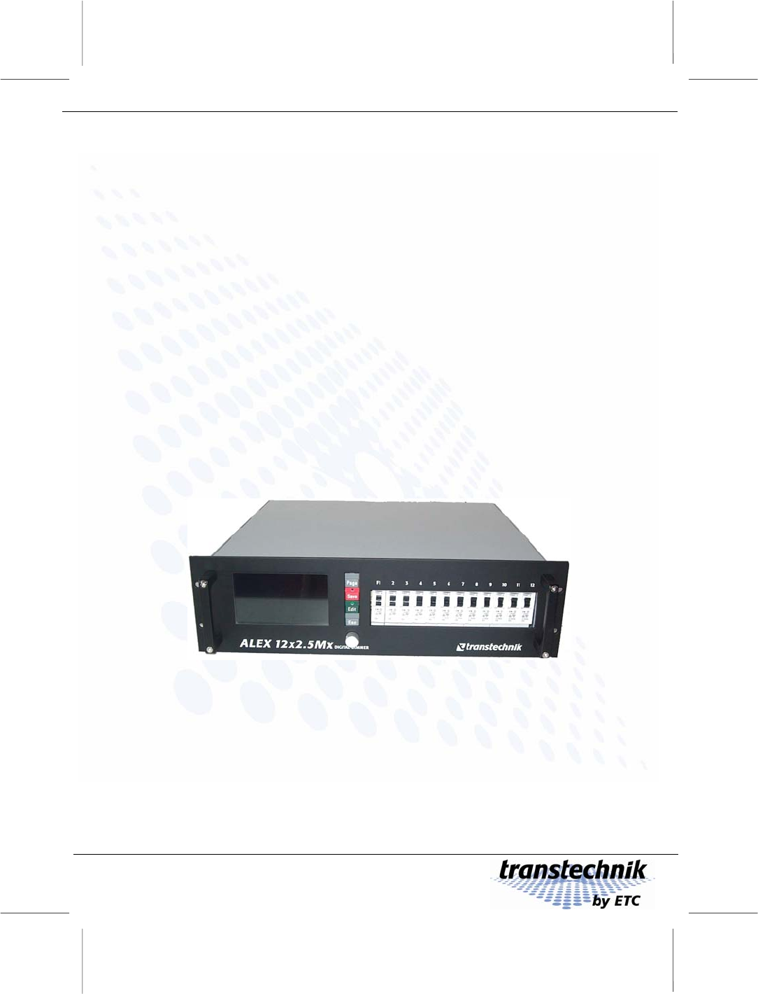
Beschreibung Meet Alex M First impressions Meet Alex M First impressions Functions Alex M allows you to: • Convert DMX control commands received from the lighting control system into voltage values for electrical loads like spotlights • Save a maximum of twelve presets and make them available for use. • Run several presets at the same time with selectable weightings. The chaser function allows you to: • Run entire lighting programs – from chases to complex sequences of stored presets.
Bedienung Operation Meet Alex M Operation Display An extremely high-contrast CFL (cathode fluorescent lamp) backlit display with a visible area of 13 x 7 centimeters and over 30,000 pixels, making it easy to read even from a considerable distance whatever the ambient lighting conditions. Menu-driven interface You operate Alex M using four keys, a rotating knob (encoder) and the menus that appear on the display.
Meet Alex M Special features Special features Thyristors The thyristors, which use phase angle control for the output voltage, each contain a separate ignition circuit for the positive and negative half-waves. This means that the output voltages of each of the dimmer units have no DC components and makes them suitable for controlling low-voltage transformers. Fan A temperature controller ensures that the fan only ever runs just as fast as is absolutely necessary.
Sicherheit Symbols Safety Safety Symbols This manual uses the symbols depicted below for Danger, Caution and Note. The meanings of these symbols are as follows: Danger This symbol indicates situations where failure to follow the instructions carefully can result in death, injury or accidents. Caution This symbol indicates situations where failure to follow the instructions carefully can cause damage to your equipment.
Safety Important rules Important rules It is not dangerous to work with Alex M. Protective insulation and a whole series of other protective measures ensure that you cannot come into contact with any harmful electric currents. However, as with all electrical equipment, you will need to observe a few simple rules: • Never switch on equipment that is obviously damaged. Send the equipment to an authorized dealer or back to the factory for repairs.
Alex M is very robust, but... Safety Alex M is very robust, but... Alex M is designed to cope with the rigors of mobile service, so it will put up with a lot. Nevertheless, you should still adhere to the following guidelines: • Only use your equipment for the purpose for which it is intended. • Never cover the front and back of your equipment in such a way that this would impede air circulation (e.g. with plastic sheeting). • Ensure that there are always sufficient openings for heat to be expelled.
Lighting in no time with Alex M 6 or 12 output channels Lighting in no time with Alex M • Alex M lets you get down to business straight away. Over the next few pages you will find an outline of the major functions for operating and adjusting the system. • For detailed information on the menu pages and all the opportunities afforded by Alex M, please turn to page 41. • You will find a list of the factory settings on page 58.
Wiring Working with Alex M Working with Alex M Wiring Not even Alex M lets you get away without setting up any cable connections: • A connection to the power supply • Connections to the required dimmer channels This is all you need to go ahead and provide lighting with Alex M. If the dimmers are to be controlled by external signals as well, you also need to connect the signal source: Control with DMX512/1990 signal Connect DMX cables to the DMX IN and DMX OUT sockets.
Working with Alex M Switching the device on Switching the device on As soon as the power (at least one phase) has been switched on, the dimmer system starts up and the welcome screen appears on the display for five seconds. The first menu page, Intensities, then appears (see page 42). Fig. 1: Welcome screen Controls All input is made using 4 keys and a rotating knob (the encoder). Menus and messages are displayed on a backlit LCD screen. Keys Scrolls from one menu page to the next.
Controls Working with Alex M The LEDs in the [Edit] and [Save] keys and the status line at the bottom of the display provide information on the current input status: Edit mode not active Status line Wheel selects Edit mode active, no values changed yet Status line Í LED on Wheel Edit mode active, at least one value changed Status line Edit to change Save confirms Í LED on Í LED on Wheel Esc quits Save confirms Esc quits Rotating knob The rotating knob has two modes: Edit mode inactive All i
Working with Alex M Preventing improper use of Alex Preventing improper use of Alex You can secure the device against inadvertent improper use by activating LOCK mode. Prerequisite for activating LOCK mode: EDIT mode must not be active. 1 Switch lock mode on or off by pressing and holding [Save] and then additionally pressing [Esc]. • In LOCK mode, menu page 1, Intensities, is displayed constantly. • The text LOCKED_MODE appears highlighted (Fig. 2).
Grundeinstellungen Basic settings Working with Alex M Basic settings Before you start, you can rest assured: The device is ready for operation immediately even if you don’t make any basic settings. Before you start working with Alex M, you should nevertheless have a look at selected basic settings (there are a total of 12). You can use them to customize Alex M to suit your exact requirements. To make working with the device easier for you, you can set the menu language and display contrast, for example.
Working with Alex M Basic settings Setting the display contrast 1 Press [Page] until menu page 4, Basic Settings, appears. 2 Turn the knob until the CONTRAST field is highlighted. 3 Press [Edit]. 4 Use the knob to set the desired contrast (factory setting: 75). 5 Press [Edit]. • Fig. 4: Basic Settings menu Active field: CONTRAST The contrast setting is saved. Resetting the dimmer processor The reset function resets all settings and parameters to the factory settings.
Basic settings Working with Alex M Selecting the source for the dimmer control signals 1 Press [Page] until menu page 4, Basic Settings, appears. 2 Turn the knob until the INPUT field is highlighted. 3 Press [Edit]. 4 Use the knob to select a signal source. (Factory setting: Dmx + Mem/Chase) Fig.
Working with Alex M Basic settings Setting the DMX start address There are two ways to set the DMX addresses: • All twelve channels receive a DMX address, which is incremented in ascending order from the start address. • Each of the twelve channels receives its own address. Setting a sequence of DMX addresses in ascending order 1 Press [Page] until menu page 4, Basic Settings, appears. 2 Turn the knob until the DMX ADDRESS field is highlighted. 3 Press [Edit].
Basic settings Working with Alex M Assigning each channel an individual DMX address 1 Press [Page] until menu page 4, Basic Settings, appears. 2 Turn the knob until the DMX ADDRESS field is highlighted. 3 Press [Edit]. 4 Turn the knob counterclockwise until the SINGLE setting appears. Fig. 8: Basic Settings menu Active field: DMX ADDRESS Selected: SINGLE • The setting SINGLE is saved, and the next line is highlighted. 5 Press [Save]. 6 Press [Page].
Weitere Grundeinstellungen Working with Alex M Basic settings Further basic settings Further basic settings can be made on menu page 4, Basic Settings, in the same way as described in the previous pages: Setting Entry field Behavior if DMX signal fails ON DMX FAIL Fade-in time for the selected auxiliary group if the DMX signal fails MEMORY TIME Minimum value for dimmer control via analog signal ANA-MIN Resetting of all preset and chase parameters CLEAR MEM/CHASE Fade-in time for intensity increme
Intensität einstellen Setting the intensity of a channel Providing stationary lighting Providing stationary lighting (manual intensity adjustment) Alex M with six or twelve output channels The screenshots used in this manual depict the menu pages for an Alex M dimmer unit with twelve output channels. If your Alex M unit has six output channels, the Intensities, Parameters and Memory/ Chaser menu pages will look rather different owing to the smaller number of output channels.
Providing stationary lighting Setting the same intensity for all channels Setting the same intensity for all channels 1 Press [Page] to call menu page 1, Intensities. 2 Use the knob to select the ALL LEV function. • The current setting is selected (75 in the figure). 3 Press [Edit] and use the knob to set the desired value. Fig. 12: ALL LEV function • The setting takes effect immediately and is displayed in the form of a transparent bar with a numeric value for each channel.
Saving current output levels as presets Providing stationary lighting Saving current output levels as presets This function saves the current intensity settings as a preset – irrespective of its composition in terms of external and internal intensities (solid and transparent bars). 1 Press [Page] to call menu page 1, Intensities. 2 Use the knob to select the MEM function. 3 Press [Edit] and use the knob to set the desired memory block number (from 1 to 12).
Providing stationary lighting Preheating Preheating Setting preheating individually for each dimmer channel The preheat intensity can be adjusted in 0.1% steps in the range from 0 to 10%. Above 10% you can change the value in 1% steps. 1 Press [Page] to call menu page 2, Parameters. 2 Use the knob to move the selection cursor to the PRE row and to the desired channel in this row. 3 Press [Edit] and use the knob to set the desired percentage for the preheat intensity (15% in the figure).
Preheating Providing stationary lighting Setting the same preheat intensity for all dimmer channels 1 Press [Page] to call menu page 2, Parameters. 2 Use the knob to move the selection cursor to the ALL input field. 3 You can set the same values here for all channels for the following: − Preheat (PRE) − Intensity limit (LIM) − Dimmer curve (DCU) Fig. 15: Setting the same preheat intensity for all channels 4 Turn the knob until ALL PRE appears.
Providing stationary lighting Intensity limit Intensity limit Setting an intensity limit 1 Press [Page] to call menu page 2, Parameters. 2 Use the knob to move the selection cursor to the LIM row and to the desired channel in this row. 3 Press [Edit] and use the knob to set the desired limit intensity value (FF = 100% in the figure). Fig. 16: Setting an intensity limit • The setting takes effect immediately.
Intensity limit Providing stationary lighting Setting the same intensity limit for all dimmer channels 1 Press [Page] to call menu page 2, Parameters. 2 Use the knob to move the selection cursor to the ALL input field. 3 You can set the same values here for all channels for the following: − Preheat (PRE) − Intensity limit (LIM) − Dimmer curve (DCU) Fig. 17: Setting the same intensity limit for all channels 4 Turn the knob until ALL LIM appears.
Providing stationary lighting Dimmer curves Dimmer curves The dimmers are controlled using characteristic curves. A curve assigns each output level (e.g. 50%) to a specified 'real' dimmer level. The dimmer curve can be used to modify the dimming behavior of a spotlight to the given requirements (e.g. to come on when a particular threshold value is achieved, unlike linear control). All dimmer curves refer to the power output. Characteristic curve LI “linear” thus means “linear power output”.
151 166 181 196 211 226 241 256 166 181 196 211 226 241 256 136 151 121 91 106 76 61 46 31 1 100 90 80 70 60 50 40 30 20 10 0 16 LG Logarithmic or voltage linear, for 115 V at an output level of 50% Providing stationary lighting Output power (%) Dimmer curves Input 100 ND Non-Dim (switching curve) 90 Output power (%) 80 70 60 50 40 30 20 10 136 121 106 91 76 61 46 31 16 1 0 Input Assigning a dimmer curve individually for each dimmer channel 1 Press [Page] to c
Providing stationary lighting Dimmer curves Assigning the same dimmer curve to all channels 1 Press [Page] to call menu page 2, Parameters. 2 Use the knob to move the selection cursor to the ALL input field. 3 You can set the same values here for all channels for the following: − Preheat (PRE) − Intensity limit (LIM) − Dimmer curve (DCU) Fig. 19: Assigning the same dimmer curve to all dimmer channels 4 Turn the knob until ALL DCU appears.
– 34 – Alex M 030430-150B Alex_M_E_150C_A5.
Providing light automatically Fading in stored presets Providing light automatically Fading in stored presets You can fade in several stored presets with individually selected weightings. 1 Press [Page] to call menu page 3, Memory/Chaser. 2 Use the knob to move the selection cursor to the MEM row and to the desired preset in this row (3 in the figure). • The bar chart displays the individual intensities of this preset. Fig.
Fading in stored presets Providing light automatically While the presets are faded in, output levels from other settings or sources continue to be output: • Internally: Manual output levels created using menu page 1, Intensities • Externally: Output levels determined by other signal sources If you want to output all presets that have been stored alone, the following prerequisites must be met: • Signal source: Mem/Chase • All manually created output levels must be at zero Displaying the contents of st
Providing light automatically Creating a chase with the chaser function Creating a chase with the chaser function Setting the fade time The fade time is the time taken for the first preset to fade in, for the first preset to crossfade to the second, and so on. 1 Press [Page] to call menu page 3, Memory/Chaser. 2 Use the knob to move the selection cursor to the FADE field. 3 Press [Edit] and use the knob to set the desired fade time (0.0 seconds in the figure). • Applies to all presets. Fig.
Creating a chase with the chaser function Providing light automatically Setting a sequence of presets You can define a sequence of 1 to a maximum of 12 presets in any order. The SEQ row on menu page 3, Memory/Chaser, contains 12 positions for this purpose that are prefilled with the 12 storable presets in ascending order (factory setting). However, any preset can be assigned to each of these sequence positions. 1 Press [Page] to call menu page 3, Memory/Chaser.
Providing light automatically Creating a chase with the chaser function Running a chase 1 Press [Page] to call menu page 3, Memory/Chaser. 2 Use the knob to move the selection cursor to the CHASE field. • The current status (STOP) is selected. 3 Press [Edit]. Fig. 27: • The status display changes to GO. Running a chase 4 Press [Save] to activate the chase.
Creating a chase with the chaser function Providing light automatically Holding/terminating a chase 1 Press [Page] to call menu page 3, Memory/Chaser. 2 Use the knob to move the selection cursor to the CHASE field. • The current status (GO__XX =) is selected. 3 Press [Edit]. • The number of the preset that has just been output disappears, but the chaser function remains active. Fig. 28: Holding a chase 4 Use the knob: • To set the HOLD function to hold the chase.
The menu pages Status line The menu pages In conjunction with the keypad and the knob, four menu pages (shown here for an Alex M with 12 channels) allow you to make all the entries you need and keep you in the picture at all times regarding the current operating status of Alex M: Menu page 1: Intensities (see page 42) Menu page 2: Parameters (see page 44) Menu page 3: Memory/Chaser (see page 46) Menu page 4: Basic Settings (see page 49) You press [Page] to cycle through these 4 menu pages.
Menu page 1: Intensities The menu pages Menu page 1: Intensities Menu page 1, Intensities, constantly displays the current output levels for all dimmer channels in a bar chart. Fig. 29: Menu page 1, Intensities, for a configuration with 12 dimmers. When there are 6 dimmers, you will, of course, only see six channelspecific indicators (e.g. bars). Output level display Menu page 1, Intensities, constantly displays the current output levels for all dimmer channels in a bar chart.
The menu pages Menu page 1: Intensities Input/display fields 1st row under bar chart Contribution made by Alex M to the output levelSpecified in percent for each channel Value range: 0 to FF (0% to 100%) Factory setting: All 0 2nd row under bar chart Status display, entry for each channel Circuit closed, no error − Circuit open (no lamp connected, spotlight defective)* E Fuse triggered P Phase error MEM X= Input field for saving the current output level as a preset X Memory block, value range: 1 to
Menu page 2: Parameters The menu pages Menu page 2: Parameters This menu page shows the individual dimmer parameters for each channel and allows you to modify them. Fig. 30: Menu page 2, Parameters, for a configuration with 12 dimmers. When there are 6 dimmers, you will, of course, only see six channel-specific displays (e.g. bars).
The menu pages Menu page 2: Parameters Input fields for each channel individually LEV Internal contribution to the output level Value range: 0 to FF (0% to 100%) STA Status display Circuit closed, no error Circuit open (no lamp connected, spotlight − defective)* E Fuse triggered P Phase error The symbol is also displayed if a lamp is not connected and output exceeds 90%. *) The display ”-” (Circuit open) is not available on units fitted with an electronic base load.
Menu page 3: Memory/Chaser The menu pages Menu page 3: Memory/Chaser Menu page 3, Memory/Chaser, allows you to activate stored presets statically or as chases. Fig. 31: Menu page 3, Memory/Chaser for a configuration with 12 dimmers. When there are 6 dimmers, you will, of course, only see six channel-specific indicators (e.g. bars).
The menu pages Menu page 3: Memory/Chaser Input/display fields OUT Contribution made by the selected preset to the current lighting. A bar shows you at a glance the weighting factor applied for the preset. Value range: 0 to FF (0% to 100%) Factory setting: 0 MEM List of stored presets (12 memory blocks). The weighting factor (the contribution made by a given preset to the current lighting) is displayed as a small bar under the preset number. The same applies to presets that are not selected.
Menu page 3: Memory/Chaser The menu pages Input/display fields (continued) CHASE Activates, holds and terminates the chaser function. GO [Save] starts the chaser function. HOLD [Save] holds the chaser function; the current output values are retained. STOP [Save] terminates the chaser function.
The menu pages Menu page 4: Basic settings Menu page 4: Basic settings This menu page shows the basic settings for the dimmer system and allows you to modify them. Fig.
Menu page 4: Basic settings The menu pages Input/display fields (continued) MEMORY TIME Fade-in time for preset XX if the DMX signal fails FREQ Display of mains frequency Display only. This is not an input field and cannot be addressed with the knob.
The menu pages Menu page 4: Basic settings Input/display fields (continued) FU-TIME Fade-in time with intensity increments. Instead of outputting an intensity increment, the device fades the increment in over the specified time to "smooth out" the incremental effect.
Menu page 4: Basic settings The menu pages Software version The software version number of the device is shown on the bottom right of the display next to the status line on menu page 4, Basic Settings. Identifying whether a base load is fitted The dimmer unit can be fitted with an optional electronic base load (“Alex MX“).
Alex-M Loader Software updates Software updates The software tool “Alex-M Loader” provides you with a simple method of updating the dimmer processor software from a PC or laptop. You will need the following cable: • 9-pin Submin-D, male to female. Pins 4, 7 and 8 must be bridged. See Fig. 35 on page 54. Fig. 34: The “Alex-M Loader” software tool 1 Use the cable to connect the RS232 submin-D socket at the rear of the unit to a serial port on the PC / laptop. 2 Start the “Alex-M Loader” software tool.
Software updates Alex-M Loader 4 Select the serial port of the PC / laptop which is being used (COM1 or COM2). 5 Switch the dimmer unit off briefly and then on again (disconnect the power supply briefly). • If the cable is connected correctly and the settings are correct, the display on the unit remains white. If, on the other hand, the welcome screen appears, it is probable that either the incorrect serial port has been selected or the cable has been connected incorrectly.
Appendix Technical data Appendix Technical data Interfaces DMX512/1990 Analog control voltages 1 x In 1 x Out (loop output) 12 x 0 V to +10 V RS-232 1x e.g. for a laptop Link 1x to link a number of devices Functions Sources of the control signals Combination of different control signals DMX512/1990 address area Auxiliary groups Chase Preheat Output level limit Alex M 030430-150B Alex_M_E_150C_A5.doc 1. 2. 3.
Technical data Selection options if DMX signal fails Surge immunity Control curves Base load Appendix 1. Last setting 2. One of the 12 auxiliary groups 3. Chase 4. All circuits dark Cold lamps can be powered up with no restrictions. 1. Linear 2. Halogen (currently not implemented) 3. Fluorescent lamps 4. Logarithmic 5. Non-Dim Integrated electronic base load for convenient dimming of fluorescent lamps (Alex MX) Output stages Rated power Minimum load 12 x 2.
Allgemeine Daten Appendix Technical data General data Mechanical design 19” rack-mountable unit as a standalone device or for mounting in a flight case or rack LCD, 130 x 70 mm, backlit CFL, 240 x 128 pixels Modern processor architecture based on SMD technology 400 V AC, 3 P + N + PE CEE 32 A or CEE 63 A 48 to 52 Hz or 58 to 62 Hz 5-pin CEE connector, 32 A or 63 A Display Computer system Power supply Power system input Load output Weight Multicore (Harting); others available on request 19", 3 HE (13
List of factory settings Appendix List of factory settings RESET DEVICE on menu page 4, Basic Settings, allows you to reset all the settings on your dimmer system to the factory settings. The menu pages Parameters and Memory/Chaser offer reset functions that only apply to certain settings. Size Value DMX start address 1 Behavior if DMX signal fails Hold Fade-in time after DMX failure 0.
Appendix Pin assignments Pin assignments Pin assignment of the load outputs (HTS plug-in connector) Alex M 12 x 2.
Pin assignments Appendix Alex M 6 x 5 kVA Upper HTS plug-in connector (CH 1-3): Pin Assignment (phase) Pin Assignment (neutral) 1 L CH 1 3 L CH 2 5 L CH 3 2 N CH 1 4 N CH 2 6 N CH 3 Lower HTS plug-in connector (CH 4-6): Pin Assignment (phase) Pin Assignment (neutral) 1 L CH 4 3 L CH 5 5 L CH 6 2 N CH 4 4 N CH 5 6 N CH 6 L Fig. 37: 6-pin HTS plug-in connector (load outputs Alex M 6 x 5 kVA) N – 60 – Alex M 030430-150B Alex_M_E_150C_A5.
Appendix Pin assignments Pin assignment for the EXT socket The 15-pin Submin-D socket EXT on the backplane of the dimmer unit serves as the feed-in for analog control signals (12 channels, 0 – 10 V). 8 7 6 5 4 3 2 1 Pin 15 Channel number 14 13 12 11 10 – 12 9 8 11 7 6 10 5 4 9 3 2 1 – GND Alex M 030430-150B Alex_M_E_150C_A5.
– 62 – Alex M 030430-150B Alex_M_E_150C_A5.
Appendix Version status Version status Manual version SW vers. Date Changes/additions 080897-120A 1.20 08.08.1997 First complete edition of the manual, German and English 171298-129A 1.29B 17.12.1998 German edition Additional menu languages, individual address assignment for each channel, preheat settings enhanced 240399-130A 1.30 24.03.1999 Addition to the manual version 080897-120A, German and English LOCK mode 241199-141A 1.41 24.11.
Integrated digital thyristor dimmer Electronic Theatre Controls GmbH Ohmstrasse 3 . 83607 Holzkirchen . Germany Tel +49 (0) 80 24 / 47 00-0 Fax +49 (0) 80 24 / 47 00-3 00 eMail Internet Deutschland@etcconnect.com www.etcconnect.