
Datasheet
Thermal-Magnetic Circuit Breakers 3600/3900
www.e-t-a.de
1719
2
1
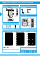
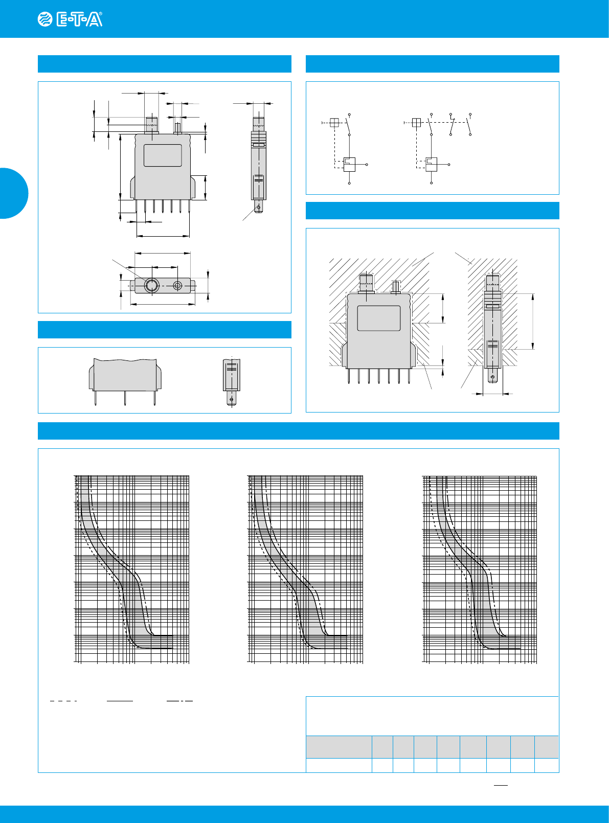
Dimensions Internal connection diagrams
14 63752
20
2
38
12.5
operating area
(reinforced insulation)
mounting area
.787
.079
1.50
.492
ø11.5
ø6.5
ø4
ø8.5
6.8
6 x 6.8 = 40.8
10
19
51
2
5
ON
11
OFF
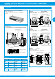
blade terminals
DIN 46244-A6.3-0.8
(QC .250)
8.5
50
20
13
43
11.5
current rating in A
2
14 63752
.157
.079
.256
.453
.335
.433
.197
2.01
.394
.268
6 x .268 = 1.61
.748
.787
1.69
.512
.335
1.97
.453
-P10-Si
3 (from I
N
=8 A)
3 (from I
N
=8 A)
7
6
line 1
2
line 1
3
2
5
4
I
>
3
I
>
with shunt terminal (standard)
and auxiliary contacts (-Si) only 3600
123
Terminal design -P10
Installation drawing
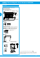
Typical time/current characteristics
+60 °C
+140 °F
+23 °C
+73.4 °F
-30 °C
-22 °F
… times rated current
12468102040
… times rated current
10000
1000
100
10
1
0.1
0.01
0.001
60 80100
Trip time in seconds
12468102040
10000
1000
100
10
1
0.1
0.01
0.001
60 80100
Trip time in seconds
Trip time in seconds
12468102040
… times rated current
10000
1000
100
10
1
0.1
0.01
0.001
60 80100
3900 0.05…10 A DC
2)
3600 8…16 A AC
1)
3600 0.05…7 A AC
1)
1)
Magnetic tripping currents are increased by 20 % on DC supplies.
2)
Magnetic tripping currents are decreased by 20 % on AC supplies.
This is a metric design and millimeter dimensions take precedence (
mm
)
inch
The time/current characteristic curve depends on the ambient temperature
prevailing. In order to eliminate nuisance tripping, please multiply the
circuit breaker current ratings by the derating factor shown below. See also
section Technical information.
Ambient temp. °F
°C
-22
-30
-4
-20
+14
-10
+32
0
+73.4
+23
+104
+40
+122
+50
+140
+60
Derating factor
0.76 0.79 0.83 0.88 1 1.08 1.16 1.24