
Datasheet
Thermal Overcurrent Circuit Breaker 3130
www.e-t-a.de
1815
2
1
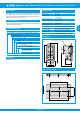
Ordering information - 1-pole
Type No.
3130 single pole thermal circuit breaker
Mounting
F snap in frame
Frame
1 standard
Number of poles
1 single pole, thermally protected
Frame mounting
0 panel thickness 1-2.5 mm (.039-.099 in)
Terminal design
P7 blade terminals DIN 46244-C-Ms-S (QC 2x.110)
H7 for terminals 1.1, 2.1 3.1 terminal screws M 3.5
for terminals 1.2, 2.2, 3.2 blade terminals (QC 2x.110)
Characteristic curve
T1 thermal 1.05-1.4 I
N
Actuator style
W rocker switch with marking „I“ and „O“
moulded in
Actuator colour
01 Q black opaque without illumination
02 Q white opaque without illumination
04 Q red opaque without illumination
14 Q R red translucent with LED-illumination
15 Q Y orange translucent with
LED-illumination
19 Q G green translucent with
LED-illumination (DC only)
Illumination voltage range*
2 10 - 14 V DC
3 20 - 28 V DC
6 90 - 140 V AC
7 185 - 275 V AC
Current ratings
0,1...20 A
3130 - F 1 1 0 - P7 T1 - W 14 Q R 3 - 5 A ordering example
* N/A for non-illuminated version
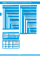
Preferred types
3130 1-pole
Standard current ratings (A)
1 2 3 4 5 8 10 15 16 20
3130-F110-P7T1-
W01Q-
x x x x x x x x x x
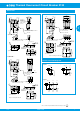
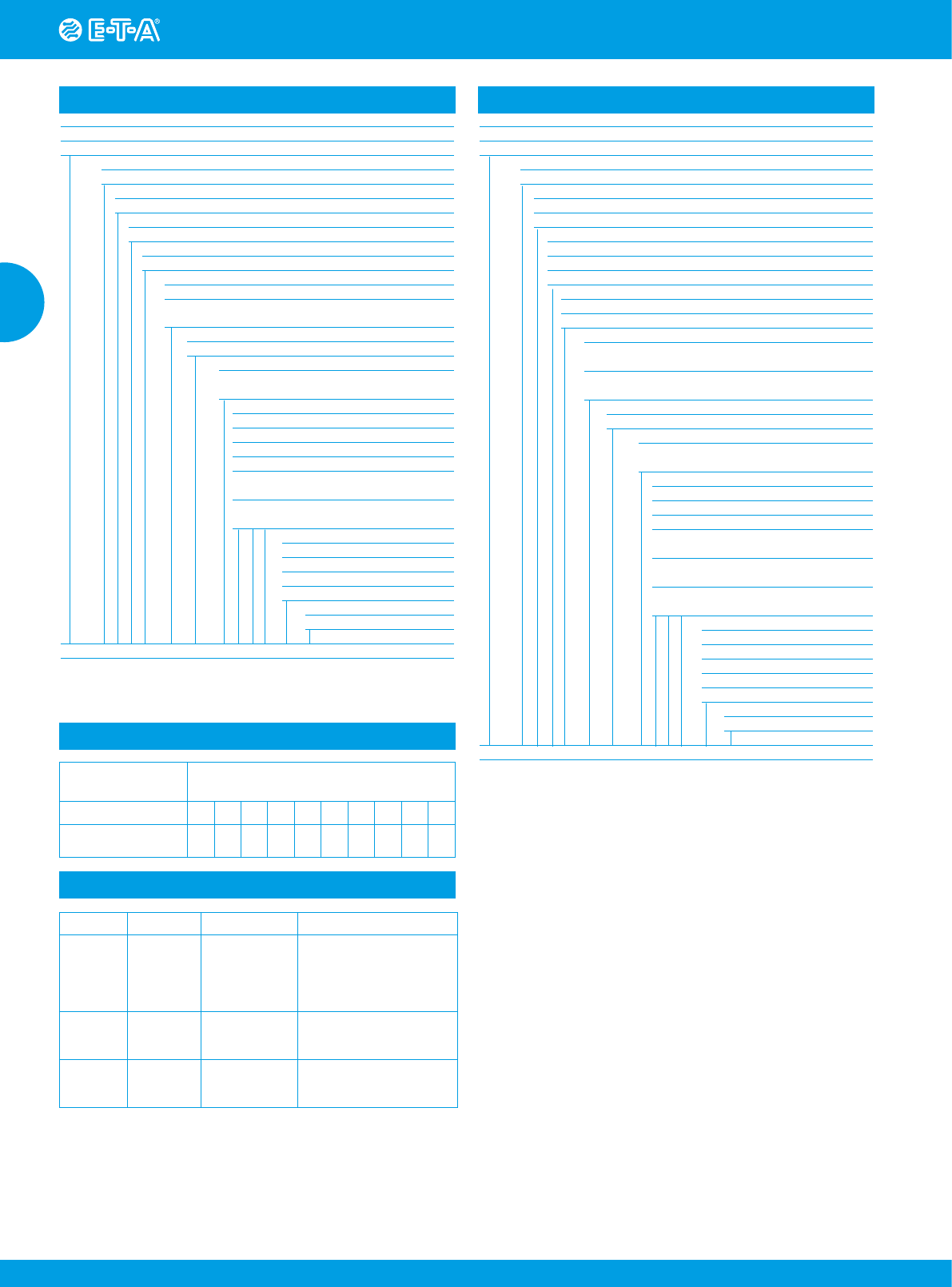
Ordering information - multipole
Type No.
3130 multipole thermal circuit breaker
Mounting
F snap in frame
Frame
1 standard
A version for X3130
Number of poles
2 2-pole thermally protected
3 3-pole thermally protected
5 2-pole, 1-pole thermally protected
Frame mounting
0 panel thickness 1-2.5 mm (.039-.099 in)
A 2-pole, version for X3130
Terminal design
P7 blade terminals DIN 46244-C-Ms-S
(characteristic curve T1)
H7 for terminals 1.1, 2.1 3.1 terminal screws M 3.5
for terminals 1.2, 2.2, 3.2 blade terminals (QC 2x.110)
Characteristic curve
T1 thermal 1.05-1.4 I
N
Actuator style
W rocker switch with marking „I“ and „O“
moulded in
Actuator colour
01 Q black opaque without illumination
02 Q white opaque without illumination
04 Q red opaque without illumination
14 Q R red translucent with
LED-illumination
15 Q Y orange translucent with
LED-illumination
19 Q G green translucent with
LED-illumination
Illumination voltage range*
2 10 - 14 V DC
3 20 - 28 V DC
6 90 - 140 V AC
7 185 - 275 V AC
8 320 - 450 V AC
Current ratings
0,1...16 A
3130 - F 1 3 0 - P7 T1 - W 14 Q R 7 - 5 A ordering example
* N/A for non-illuminated version
Preferred types
Approvals
Authority Standard Rated voltage Current ratings
VDE IEC/EN
60934
AC 240 V
AC 240/415 V
DC 50 V
DC 50 V
DC 28 V
0.1 A…20 A (single pole)
0.1 A…16 A (multipole)
0.1 A…8 A (single pole)
0.1 A…16 A (multipole)
0.1 A…20 A (single pole)
UL UL 1077
AC 250 V
AC 250 V
DC 50 V
0.1 A…16 A (1 + 2 pole)
0.1 A…12 A (3 pole)
0.1 A…16 A (1 – 3 pole)
CSA C22.2 No
235
AC 250 V
AC 250 V
DC 50 V
0.1 A…16 A (1 + 2 pole)
0.1 A…12 A (3 pole)
0.1 A…16 A (1 – 3 pole)