
Datasheet


www.e-t-a.de
16
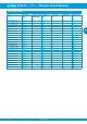
3120-N...-...T1-... Thermal Circuit Breaker
1930
1
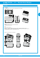
Typical applications
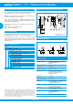
Description X3120-U undervoltage release module
Order numbering code
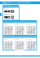
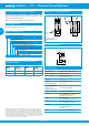
Schematic diagrams
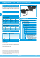
Technical data
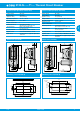
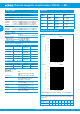
Dimensions – undervoltage release module
1 blade terminal herausgeführt
X3120-U01…
blade terminal
2.8 x 0.8
flat head screw M3.5x6
for mains connection
tightening torque max. 0.8 Nm
21
.827
22
.866
21
.827
6.6
.260
23,5
.925
33.5
1.32
15°
7.6
.299
41
+0,1
- 0,2
1.61
+.004
- .008
Without separate
terminal(s): X3120-U00…
Dimensional drawings of the
standard version of 3120-N
please see page 6-8
All machines that could cause personal injury upon automatic re-start,
e.g. drilling machines, electric saws, meat cutting machines etc.
The X3120-U02 version allows set up of a cost-effective safety
circuit via the physically isolated undervoltage release module, which
enables implementation for example of a remote disconnection with
emergency stop.
12(k)12(k) 12(k)
X3120-U00… X3120-U01… X3120-U02…
line
12(i) 22(i)
22(k)
U<
11
21
load
line
12(i) 22(i)
22(k)
U<
11
21
load
line
line
12(i) 22(i)
22(k)
U<
11 21
load
line
A2
A1 A2
Type No.
X3120 module for type 3120-N
Module
U undervoltage release module
Design
00 standard (without separate connections)
01 1 blade terminal 2.8x0.8
02 2 blade terminals 2.8x0.8
Voltage ratings
00 AC 230/240 V 50/60 Hz
01 AC 120 V 50/60 Hz
02 AC 100 V 50/60 Hz
03 DC 24 V
04 AC 400 V 50/60 Hz
Supply status
M module mounted to circuit breaker 3120-N
X3120- U 00 00 M ordering example
All information and data given on our products are accurate and reliable to the best of our
knowledge, but E-T-A does not accept any responsibility for the use in applications which are
not in accordance with the present specification. E-T-A reserves the right to change specifi-
cations at any time in the interest of improved design, performance and cost effectiveness,
Dimensions are subject to change without notice. Please enquire for the latest dimensional
drawing with tolerances if required. All dimensions, data, pictures and descriptions are for
information only and are not binding. Amendments, errors and omissions excepted. Ordering
codes of the products may differ from their marking.
Voltage ratings: AC 100 V; AC 120 V; AC 230/240 V;
AC 400 V (50/60 Hz)
DC 24 V
Voltage tolerances + 10 %/- 15 %
Typical life 20,000 cycles
Current consumption approx. 2.5 mA
Release values 0.2 x U
N
< U < 0.7 x U
N
(at a rated voltage of AC 100 V
the device can trip at 70 V and
must trip at 20 V)
Trip time < 20 ms
Reset value ≥ 85 % U
N
Ambient temperature -30 … 60 °C
Vibration 8 g (57-500 Hz), ± 0.61 mm (10-57 Hz)
test to IEC 60068-2-6, test Fc
10 frequency cycles/axis
Shock 30 g (11 ms)
test to IEC 60068-2-27, test Ea
Corrosion 48 hours at 5 % salt mist,
test to IEC 60068-2-11, test Ka
Humidity 240 hrs in 95 % RH
test to IEC 60068-2-78,
test Cab
Mass approx. 56 g (including base unit)
The undervoltage release module reliably excludes personal injury
through automatic re-start after voltage dip or power failure.
Note: Basic unit 3120-N...-H7 or -G7 requires screw terminals. Not
possible in combination with PT terminals.
Please observe the following in combination with design version 4:
In the event of voltage dip or power failure, the undervoltage release
module trips the circuit breaker.
The rocker actuator will go into centre position. Reset is effected
in two steps:
Step 1: Switch rocker into OFF position.
Step 2: Reset circuit breaker.