
Datasheet


www.e-t-a.de
19
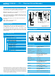
Thermal-magnetic circuit breaker 3120-N...-...M1-...
1930
1
3120-N...-...T1-... Thermal Circuit Breaker
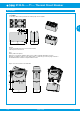
Description
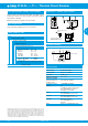
Typical applications
The 3120-N...-...M1-... thermal-magnetic circuit breaker/switch
combination unites overcurrent protection and the function of an ON/
OFF switch within a single component. The integral thermobimetal
ensures ideally matched overload protection. The magnetic trip mod-
ule trips the circuit breaker/switch combination at overload currents
from four times rated current within milliseconds.
The 3120-N...-...M1-... meets the fire resistance requirements to
EN 60335-1: 2007-02 Household and similar electrical appliances
– Safety.
Electric motors, household appliances and office machines, electrical
tools, power supplies, charging rectifiers
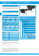
Current ratings and internal resistance values
Current rating
(A)
Internal resistance per pole (Ω)
thermal-magnetic thermal 1.15 -1.38 x I
N
0.1 165 94
0.2 42.5 24
0.3 20.2 12
0.4 9.7 5.40
0.5 7.17 4.30
0.6 4.9 3
0.8 2.65 1.50
1 1.49 0.9
1.2 1.25 0.7
1.5 0.74 0.45
2 0.49 0.29
2.5 0.20 0.0785
3 0.14 0.0595
3.5 0.114 0.0565
4 0.092 0.0435
5 0.06 0.0325
6 0.043 0.0215
7 0.030 0.0215
8 0.029 0.02
10 0.021 0.02
12 < 0.02 < 0.02
14 < 0.02 < 0.02
15 < 0.02 < 0.02
16 < 0.02 < 0.02
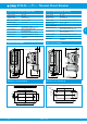
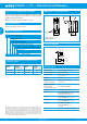
Dimensions – magnetic trip module
blade terminals
6.3 x 0.8
21
0.826
flat head screw
M3.5x6 for mains
connection
tightening torque
max. 0.8 Nm
Dimensional drawings of the
standard version of 3120-N
please see page 6-8
10
18
14
30
9
0.393
1.181
0.354
41
3.5
15.5
0.708
0.551
1.614
0.137
0.610
21
11
I
>
line
12(i) 22(i)
12(k) 22(k)
12
21
11
I
>
line
12(i)
22(i)
12(k)
12
11
I
>
line
12(i)
22(i)
12(k)
12
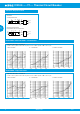
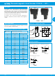
therm.-magn. protection on one pole
therm.-magn. protection on one pole
thermally protected on the other pole
therm.-magn. protection on one pol
e
unprotected on the other pole
Schematic diagrams
3120-N...-... M1-...