
Datasheet

www.e-t-a.de
3
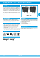
3120-N...-...T1-... Thermal Circuit Breaker
1930
1
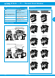
3120-N...-...T1-... Thermal Circuit Breaker
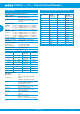
Order numbering code
Type No.
3120 thermal rocker-actuated circuit breaker/switch combination
Mounting method
N3 snap-in, mounting cut-out 50.5 x 21.5 mm
N5 snap-in, mounting cut-out 44.5 x 22 mm
Number of poles
1 1-pole switching, 1-pole thermally protected
2 2-pole switching, 2-pole thermally protected
5 2-pole switching, 1-pole thermally protected
Style
1 standard
3 with actuator guard
4 with water splash protection (IP65)
6 version for appliance inlet modules
X3120-A/-B (only for mounting method N5)
A with actuator guard and cross-hole
(for optional interlock)
Terminal design
PT push-in terminals
P7 blade terminals
H7 as P7, terminals 11 and 21 with flat head
screws M3.5 - standard for units with
undervoltage release module
N7 as P7, with additional shunt terminals 12(i) and 22(i)
G7 as N7, terminals 11 and 21 with additional flat
head screws M3.5
Trip curve
T1 thermal trip
Actuator
W rocker
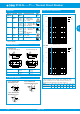
Rocker colour and illumination
01 . black without illumination
02 . white without illumination
04 . red without illumination
12 . Y white with illumination
14 . R red with illumination
15 . Y orange with illumination
16 . T blue with illumination
19 . G green with illumination
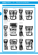
Marking of rocker actuator
rocker style
A (not for style 4)
D
F
K
L
X
Illumination voltage range
(= operating voltage)
1 DC 12 V
2 DC 24 V
3 AC 115 V
4 AC 230 V
5 DC 48 V
6 AC 400 V (for 2-pole versions
up to 16 A)
Current ratings
0.1 ... 20 A
3120-N5 2 4 - PT T1-W 19 D G 4 - 16 A ordering example
A D F K L X
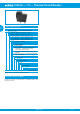
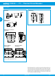
Order numbering code
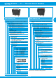
Type No.
3120 thermal circuit breaker/switch combination with push button
actuation
Mounting method
N3 snap-in, mounting cut-out 50.5 x 21.5 mm
N5 snap-in, mounting cut-out 44.5 x 22 mm
Number of poles
1 1-pole switching, 1-pole thermally protected
2 2-pole switching, 2-pole thermally protected
5 2-pole switching, 1-pole thermally protected
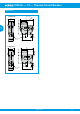
Style
D with actuator guard
E with actuator guard and water splash cover
F with power-on protection
V with power-on protection and water splash cover
Terminal design
PT push-in terminals
P7 blade terminals
H7 as P7, terminals 11 and 21 with flat head
screws M3.5 - standard for units with
undervoltage release module
N7 as P7, with additional shunt terminals 12(i)
and 22(i)
G7 as N7, terminals 11 and 21 with additional
flat head screws M3.5
Trip curve
T1 thermal trip
Actuator
S two push buttons
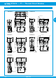
Colour of push button/illumination
(style D and F without water splash
protection)
GRD green/red without illumination
GRDG green with LED illumination/red
without illumination
Colour of push button/illumination
(style E and V with water splash
protection)
GRX green/red without illumination
GRXG green with LED illumination/red
without illumination
Illumination voltage range
(= operating voltage)
1 DC 12 V
2 DC 24 V
3 AC 115 V
4 AC 230 V
5 DC 48 V
6 AC 400 V (for 2-pole versions
up to 16 A)
Current ratings
0.1 ... 20 A
3120-N3 5 V - PT T1-S GRXG - 20 A ordering example
Please observe our minimum ordering quantities.