
Datasheet

www.e-t-a.de
18
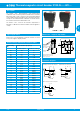
3120-N...-...T1-... Thermal Circuit Breaker
1930
1
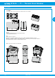
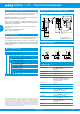
A module which adds remote trip capability to all versions of type
3120-N. A voltage applied across the coil will cause trip of the main
switch/circuit breaker mechanism.
Note: Not possible in combination with PT terminals.
Description X3120-M remote trip module
Typical applications
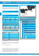
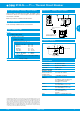
Order numbering code
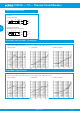
Schematic diagram
Technical data
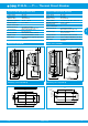
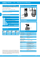
Dimensions – remote trip module
blade terminals
6.3 x 0.8
21
18
14
30
9
10.7
.827
1.18
.709
.551
.354
.421
Dimensional drawings of the
standard version of 3120-N
please see page 6-8
Electrical remote trip of safety systems.
12(k)
line
12(i) 22(i)
22(k)
11
21
load
FA
12
remote trip
12(n)
module
mounted
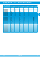
Standard voltage ratings and typical internal
resistance values
Type No.
X3120 module for type 3120-N
Module
M magnetic trip module
Design
2 magnetic remote trip coil
Terminal design
P7 blade terminals DIN 46244-A6.3-0.8
Supply status
M module mounted to circuit breaker 3120-N
Voltage ratings
AC 120, 230 V
DC 12, 24 V
X3120- M 2 P7 M -12 V ordering example
All information and data given on our products are accurate and reliable to the best of our
knowledge, but E-T-A does not accept any responsibility for the use in applications which are
not in accordance with the present specification. E-T-A reserves the right to change specifi-
cations at any time in the interest of improved design, performance and cost effectiveness,
Dimensions are subject to change without notice. Please enquire for the latest dimensional
drawing with tolerances if required. All dimensions, data, pictures and descriptions are for
information only and are not binding. Amendments, errors and omissions excepted. Ordering
codes of the products may differ from their marking.
Voltage
ratings
Internal
internal
resistance (Ω)
Voltage
ratings
internal
internal
resistance (Ω)
DC 12 V 0.78 AC 120 V 71.0
DC 24 V 3.3 AC 230 V 312
Voltage ratings: AC 120...230 V; DC 12...24 V
Power consumption approx. 200 Watt
Pulse operation 20 ms < t
ON
< 100 ms
t
OFF
> 10 sec
Trip time < 20 ms
Typical life 50,000 operations at U
N
ambient temperature -30 … 60 °C
Dielectric strength
Between main
and trip current circuit
test voltage AC 3,000 V
Insulation resistance > 100 MOhm (DC 500 V)
Vibration 8 g (57-500 Hz), ± 0.61 mm (10-57 Hz)
test to IEC 60068-2-6, test Fc
10 frequency cycles/axis
Shock 30 g (11 ms)
test to IEC 60068-2-27, test Ea
Corrosion 96 hours at 5 % salt mist,
test to IEC 60068-2-11, test Ka
Humidity 240 hrs in 95 % RH
test to IEC 60068-2-78,
test Cab
Mass approx. 56 g (including base unit)