
Datasheet
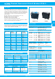

Thermal Overcurrent Circuit Breaker 3120-F...
www.e-t-a.de
Issue D
2 - 69
2
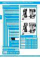
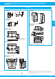
Dimensions
25
16
7
33
35
10.7
21
54
10
3
3.5
15.5
41
blade terminals DIN 46244-C-Ms-S
(QC 2x. 110)
flat head screw ISO1580 M3.5x5-MS
tightening torque max. 0.8 Nm
Actuating force max. 35 N
optional illumination in ON position
OFF position
12(i) 12(k) 11
.630
.984
2.13
.394
.118
.138
.610
1.61
.276
1.38
1.30
.421
.827
Style F3.1
collar height 1 mm/.039 in.
Installation drawing
mounting area
operating area
710
15.5
7
7
8
10
12(i) 12(k) 11
When installing the circuit breaker apply pressure on bezel only
.276
.276
.315 .276 .394
.610
.394
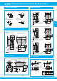
Mounting style variants
Style F 3.4
collar height 2 mm (.079 in.), with water splash protection
Style F 3.3 collar height 9 mm (.354 in.)
27
19.5
1.30
10.7
10
33
3.8
.421
.827
.150
.394
.768
1.06
21
Style F 5.1
3.5
.138
15.5
Optional illumination
48
10
3
41
12(i) 12(k) 11
.118
.394
.610
1.61
1.89
3.5
.138
56
15.5
35
3
.118
.394
.610
1.61
1.38
41
10
2.21
12(i) 12(k) 11
25
1.30
blade terminals DIN 46244-C-Ms-S
(QC 2x.110)
flat head screw M3.5x5-MS ISO1580
tightening torque max. 0.8 Nm
10.7
19.5
9
33
35
.421
.827
1.38
.354
.768
.984
21
54
12(i) 12(k) 11
15.5
3.5
35
3
.118
.394
.138
.610
1.61
1.38
41
10
2.13
25
blade terminals DIN 46244-C-Ms-S
(QC 2x.110)
10.7
21
16
7
33
35
.421
.827
1.30
1.38
.276
.630
.984
blade terminals DIN 46244-C-Ms-S
(QC 2x.110)
flat head screw M3.5x5-MS ISO1580
tightening torque max. 0.8 Nm
flat head screw M3.5x5-MS ISO1580
tightening torque max. 0.8 Nm
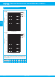
Internal connection diagrams
11
21
line
12(i)
12(k)
22(i)
22(k)
load
12(k)
load
11
line
12(i)
12(k)
22(i)
load
11
21
line
12(i) 22(i)
2-pole,
thermally protected on both poles
2-pole,
thermally protected on one pole only
1-pole,
thermally protected
2-pole,
unprotected
12(i) 22(i)
Netz
Last
11
21
This is a metric design and millimeter dimensions take precedence (
mm
)
inch
Cut-out dimensions
.039-.250
1-6.35
Cut-out for mounting style -F3
with rocker and push button
Cut-out for mounting
style -F5/-F7
with rocker
min. 2.5
min .098
max. R2
max .079
50.5
+0.3
21.5
+0.2
max. R0.3
1.99
+.012
.846
+.008
max .012
- 0.4
-.016
- 0.2
-.008
±0.05
±.002
1-4 mm
.039-.157 in.
panel
thickness
1.2
+0.4
.047
+.016
1.6
+0.8
.063
+.031
2.4
+1
.094
+.039
Edges of working parts: ISO 13715
max. R1.5
max .059
min. 2
min .079
dimension
“A”
45
1.77
+.008
- .002
+0,2
- 0.05
45
1.77
45
1.77
mm
inch
mm
inch
+1.1
- 0.05
+2.2
- 0.05
+.043
- .002
+.087
- .002
- 0.4
-.016
- 0.2
-.008
±0.05
±.002
1.75
+.008
22
+0.3
max. R0.3
44.5
+0.2
max .012
.866
+.012