
Datasheet
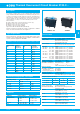

Thermal Overcurrent Circuit Breaker 3120-F...
www.e-t-a.de
Issue D
2 - 68
2
0
I
I
0
ON
OFF
ADFX
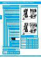
Type No.
3120 rocker switch/circuit breaker
Mounting
F snap in frame
Size of frame
3 to fit mounting cut-out 50.5 x 21.5 mm
panel thickness: 1-6.35 mm (.039-.250 in)
5 to fit mounting cut-out 44.5 x 22 mm
panel thickness: 1-4 mm (.039-.157 in)
7 to fit mounting cut-out 45 x 33.7 mm
panel thickness: 1.2-2.4 mm (.047-.094 in)
Number of poles
0 2-pole, unprotected, switch only
1 1-pole, thermally protected
2 2-pole, thermally protected
5 2-pole, 1-pole thermally protected
Mounting frame design (F3 & F5)
1 collar height 1 mm
3 collar height 9 mm
4 collar height 2 mm with water splash protection (IP54)
Mounting frame design (F7)
R
black
T black with snap-on splash cover
Terminal configuration
P7
blade terminals, standard for curve T1
(thermal circuit breaker)
H7 as P7, terminals 11 and 21 with flat head screws M3.5
– standard for units with undervoltage release module
N7 as P7, but with additional shunt terminals 12(i) and 22(i) –
standard for version Q1 (switch only)
Characteristic curve
T1 thermal 1.01 - 1.4 x I
N
Q1 switch only
Actuator style
W
standard rocker (F3 & F5)
A specially designed rocker (F7)
Colour and Illumination
01 .
rocker black opaque
without illumination
02 .
rocker white opaque
without illumination
04 .
rocker red opaque without illumination
14 . R rocker red translucent with
LED-illumination
15 . Y rocker orange translucent with
LED-illumination
19 . G rocker green translucent with
LED-illumination
Rocker markings for F3 and F5
A
D
F
Q
X
Rocker markings for F7
Q
»I« and »O« moulded in
Illumination voltage range
1 10 - 14 V DC
2 20 - 28 V DC
3 90 - 140 V AC
4 185 - 275 V AC
Current ratings
0.1...20 A
3120 - F 7 2 R - P7 T1 - A 14 Q R 4 - 10 A ordering example
3120 - F . 0 . - N7 Q1 - W .. . . . - 20 A (switch)
Ordering information
Q: as D, but
moulded in
X: without markings
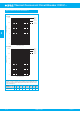
Preferred types
F7/2-pole
protected
Standard current ratings (A)
0.511.52345681012151620
3120-F72R-P7-
T1-A14QQR4-
xxxxxx xxxxxxxx
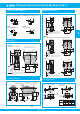
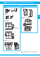
Dimensions
33
1.30
.453
15.5
15.5
25
44.2
-0.2
flat head screw ISO1580 M3.5x5-MS
tightening torque max. 0.8 Nm
blade terminals DIN 46244-C-Ms-S
(QC 2 x .110)
8.9
33
10.7
21
10
3
3.5
41
12(i) 12(k) 11
48
±0.2
3
LINE
34
44.8
10
12(i) 12(k) 11
11.5
LINE
18.6
60
.984
.610
1.89
±.008
1.74
-.008
.118
1.30
.350
.421
.827
.118
.138
.394
.610
1.61
1.76
2.36
1.34
.732
.394
.827
blade terminals DIN 46244-C-Ms-S
(QC 2 x .110)
10.7
21
.421
15.5
3
41
.118
.138
.610
1.61
3.5
Style F7.R
Style F7.T
flat head screw ISO1580 M3.5x5-MS
tightening torque max. 0.8 Nm
Preferred types Standard current ratings (A)
Preferred types
F3/1-pole protected
0.512345681012151620
3120-F311-P7T1-
W02D-
x x xxxx x x
Preferred types
F3 /2-pole protected
0.512345681012151620
3120-F321-P7T1-
W01D-
xxxxx xxxxxxxx
Preferred types
F5/2-pole protected
0.512345681012151620
3120-F521-P7T1-
W01D-
xxxx xxxxxxxx
Preferred types
Preferred types
WE
N
WE
N