
Datasheet
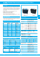

Thermal Overcurrent Circuit Breaker 3120-F...
www.e-t-a.de
Issue D
2 - 67
2
Description
Typical applications
Approvals
Technical data
An extremely versatile range of rocker switch/thermal circuit breakers
(S-type TO CBE to EN 60934 with trip free mechanism) offering the choice
of single pole, double pole with single pole protection, and double pole
with protection on both poles. Designed for snap-in panel mounting with
versions available for three different panel cut-out sizes. Illumination is
optional and there is a range of colours and markings for the rocker.
Add on modules:
● Under voltage release coil (for double pole versions only).
● Magnetic trip coil for short circuit protection.
● Magnetic trip coil for remote relay trip.
● Auxiliary contacts for status signalling.
Approved to CBE standard EN 60934 (IEC 60934).
Meets the requirements regarding fire resistance of EN 60335-1 : 2007-02
Safety of household and similar electrical appliances.
Motors, transformers, solenoids, extra low voltage wiring systems, office
machines, electro-medical equipment, power supplies, communications
systems, medical equipment to EN 60601.
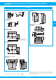
3120-F3...F5 3120-F7
For further details please see chapter: Technical Information
Voltage rating AC 240 V; DC 50 V
(AC 415 V to special order)
(UL: AC 250 V; DC 50 V)
Current ratings 0.1...20 A
(up to 30 A to special order, single pole only)
Typical life 1-pole
AC 240 V: 0.1...20 A 30,000 operations at 1 x I
N
, inductive
DC 50 V: 0.1...4 A 30,000 operations at 1 x I
N
, inductive
4.5...16 A 30,000 operations at 1 x I
N
, resistive
DC 28 V: 0.1...20 A 30,000 operations at 1 x I
N
, inductive
2-pole
AC 415 V: 0.1...16 A 10,000 operations at 1 x I
N
, inductive
AC 240 V: 0.1...16 A 50,000 operations at 1 x I
N
, inductive
17...20 A 30,000 operations at 1 x I
N
, inductive
DC 50 V: 0.1...16 A 50,000 operations at 1 x I
N
, inductive
17...20 A 10,000 operations at 1 x I
N
, inductive
Ambient temperature -30...+60 °C (-22...+140 °F)
Insulation co-ordination rated impulse pollution
(IEC 60664 and 60664 A withstand voltage degree
2.5 kV 2
reinforced insulation in operating area
Dielectric strength
(IEC 60664 and 60664A) test voltage
operating area AC 3,000 V
between poles (2-pole) AC 1,500 V
Insulation resistance > 100 MΩ (DC 500 V)
Interrupting capacity I
cn
0.1...2 A 10 x I
N
2.5...20 A 250 A 2-pole, or 150 A 1-pole
Interrupting capacity (UL 1077)
Degree of protection operating area IP40
(IEC 60529/DIN 40050) (IP54 with water splash protection)
terminal area IP00
Vibration 8 g (57-500 Hz), ± 0.61 mm (10-57 Hz)
to IEC 60068-2-6, test Fc
10 frequency cycles/axis
Shock 30 g (11 ms)
to IEC 60068-2-27, test Ea
Corrosion 96 hours at 5 % salt mist,
to IEC 60068-2-11, test Ka
Humidity 240 hours at 95 % RH,
to IEC 60068-2-78, test Cab
Mass approx. 33 g (double pole)
approx. 27 g (single pole)
Standard current ratings and typical internal resistance values
Illumination voltage/power consumption
operating voltage power consumption
Y + R G
12 V DC 2 mA 3.5 mA
24 V DC 2 mA 3.5 mA
115 V AC 0.9 mA 2.8 mA
230 V AC 0.9 mA 2.8 mA
Current rating
(A)
Internal
resistance
per pole (Ω)
Current rating
(A)
Internal
resistance
per pole (Ω)
0.1 94 4 0.0435
0.2 24 4.5 0.0435
0.3 12 5 0.0325
0.4 5.30 6 0.0215
0.5 4.20 7 0.0165
0.6 2.90 8 0.0165
0.8 1.50 10 < 0.02
1 0.9 12 < 0.02
1.2 0.80 14 < 0.02
1.5 0.45 15 < 0.02
2 0.27 16 < 0.02
2.5 0.0785 18 < 0.02
3 0.0595 20 < 0.02
3.5 0.0565
Authority Voltage ratings Current ratings
VDE (EN 60934) AC 240 V; DC 28 V
DC 50 V
DC 50 V
0.1...20 A
0.1...20 A 2-pole
0.1...10 A 1-pole
UL, CSA AC 250 V; DC 50 V 0.1...20 A
CCC AC 250 V; DC 50 V 0.1...20 A
I
N
U
N
I
nc
1, 2-pole 0.1...20 A AC 250 V 5000 A
1, 2-pole 0.1...20 A DC 50 V 1000 A