
Datasheet


Thermal-Magnetic Circuit Breaker 2210-T2..Thermal-Magnetic Circuit Breaker 2210-T2..
www.e-t-a.de
1912
4
1
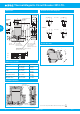
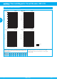
Installation drawing
Dimensions
12A
M1
Si-terminal M3
max. 1.5 mm
2
(AWG 16) (rigid conductor)
tightening torque 0.5 Nm
.295
12-14
.472-.551
.354-.472
9-12
unit I
unit II
unit III
44
30.5
18
12.5
12.5
40
5.5
37.5
OFF
ON
78.5
12.5
20
Si
1
Si
2
12
15
88.5
42.5
7.5
5.5
11.5
25
slot fitting labels from
Phoenix
Weidmüller
Wieland
G-profile
EN 50035-G32
symmetric rail
EN 50022-35x7.5
EN 50022-35x15/1.5
main contact terminal
max. 6 mm
2
(AWG 10)
(rigid conductor)
tightening torque 0.5 Nm
12A
M1
45
.787
1.77
.217
1.67
1.57
.472
.591
toggles linked
for multipole
devices
11.5
.453
1.73
3.09
3.48
.709
.984
1.20
1.48
.453
.492 .492
.492
.217
12A
M1
Si
1
Si
2
operating area
(reinforced insulation)
mounting area
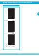
Internal connection diagrams
OFF position ON position
N/O contact
N/C contact
0I 113
2
0I 111
2
I
>
0I
1
13
2
0I 111
2
line line
line line
(Si)
(Si)
(Si) (Si)
(Si) (Si)
12 12
(Si) (Si)
14 14
I
>
I
>
I
>
...-H131-...
...-H121-...
56
1
2
4
3
This is a metric design and millimeter dimensions take precedence (
mm
)
inch
Shock directions
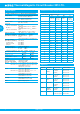
Cable cross section
Conductor Main contacts 1 & 2 Aux. contact IN
rigid
min. 0.2 mm²
max. 6 mm²
0.2 mm²
1.5 mm²
flexible
min. 0.2 mm²
max. 4 mm²
0.2 mm²
1.0 mm²
flexible with wire end ferrule
without plastic sleeve
min. 0.25 mm²
max. 4 mm²
0.25 mm²
1.0 mm²
flexible with wire end ferrule
with plastic sleeve
min. 0.25 mm²
max. 2.5 mm²
0.25 mm²
0.75 mm²