
Datasheet
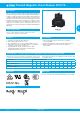


Thermal-Magnetic Circuit Breaker 2210-T2..Thermal-Magnetic Circuit Breaker 2210-T2..
www.e-t-a.de
1912
2
1
Technical data
For further details please see chapter: Technical Information
Voltage rating AC 250 V; 3 AC 433 V (50/60 Hz); DC 65 V
(UL: AC 277/480 V; DC 65 V)
Current rating range 0.1...32 A for curves M1, T1
0.1...16 A for curves F1, F2
Auxiliary circuit 1 A, AC 240 V / DC 65 V, resistive
(min. 10 V / 10 mA)
Typical life
3 AC 433 V; AC 250 V: 0.1...25 A
10,000 operations at 1 x I
N
, inductive
DC 65 V: 0.1...32 A
10,000 operations at 1 x I
N
, inductive
3 AC 433 V; AC 250 V: 32 A
6,000 operations at 1 x I
N
, resistive
Ambient temperature -30...+60 °C (-22...+140 °F) T 60
Insulation co-ordination rated impulse pollution
(IEC 60664 and 60664 A) withstand voltage degree
2.5 kV 2
reinforced insulation in operating area
Dielectric strength
(IEC 60664 and 60664A) test voltage
operating area AC 3,000 V
main/aux. circuit AC 3,000 V
pole/pole AC 1,500 V
Insulation resistance > 100 MΩ (DC 500 V)
Interrupting capacity I
cn
0.1...5 A 400 A
6...32 A 800 A
curves F1, F2, M1, T1: 0.1...16 A 2,500 A (at DC 32 V)
Interrupting capacity (UL 1077)
Degree of protection operating area IP30
(IEC 60529/DIN 40050) terminal area IP20
Vibration curves F1, F2: 3 g (57-500 Hz), ± 0.23 mm (10-57 Hz)
curves M1, T1: 5 g (57-500 Hz), ± 0.38 mm (10-57 Hz)
to IEC 60068-2-6, test Fc
10 frequency cycles/axis
Shock curves F1, F2: 25 g (11 ms), directions 1, 2, 3, 4, 5
10 g (11 ms), direction 6
curves M1, T1: 25 g (11 ms), directions 1, 2, 3, 4, 5
20 g (11 ms), direction 6
to IEC 60068-2-27, test Ea
Corrosion 96 hours at 5 % salt mist
to IEC 60068-2-11, test Ka
Humidity 240 hours at 95 % RH
to IEC 60068-2-78, test Cab
Mass approx. 60 g per pole
I
N
0.1...16 A 20...25 A
AC 277 V 1-pole 5,000 A 2,000 A
AC 277/480 V
2-/3-pole 5,000 A 2,000 A
DC 65 V 2,000 A 2,000 A
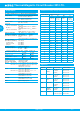
Standard current ratings and typical internal resistance values
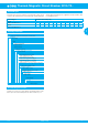
Approvals
Current rating (A) Internal resistance (Ω)
F1 F2 M1 T1
fast acting
for DC only
fast acting
delay for
AC + DC
standard for
AC+DC
delayed low
resistance
for AC only
0.1 162 162 92 81
0.2 39.3 39.3 26.1 24.2
0.3 17.5 17.5 11.6 10.4
0.4 9.2 9.2 6.6 6.0
0.5 6.8 6.8 4.1 3.9
0.6 4.2 4.2 3 2.7
0.8 2.8 2.8 1.65 1.53
1 1.6 1.6 1.10 0.98
1.5 0.78 0,78 0.47 0.42
2 0.42 0,42 0.28 0.24
2.5 0.26 0.26 0.183 0.17
3 0.18 0.18 0.124 0.12
4 0.12 0.12 0.077 0.073
5 0.092 0.092 0.063 0.055
6 0.054 0.054 0.045 0.039
8 0.025 0.025 ≤ 0.02 ≤ 0.02
10 0.022 0.02 ≤ 0.02 ≤ 0.02
12 ≤ 0.02 ≤ 0.02 ≤ 0.02 ≤ 0.02
16 ≤ 0.02 ≤ 0.02 ≤ 0.02 ≤ 0.02
20 - - ≤ 0.02 ≤ 0.02
25 - - ≤ 0.02 ≤ 0.02
32 - - ≤ 0.02 ≤ 0.02
Authority Standard Rated voltage Current ratings
VDE IEC/EN
60934
3 AC 433 V
AC 250 V
DC 65 V
0.1 A…32 A
0.1 A…32 A
0.1 A…32 A
UL UL 1077 AC 277/480 V
AC 277 V
DC 65 V
0.1 A…32 A
0.1 A…32 A
0.1 A…32 A
CSA C22.2 No
235
AC 277/480 V
AC 277 V
DC 65 V
0.1 A…32 A
0.1 A…32 A
0.1 A…32 A
CQC GB 17701 AC 250/433 V
AC 250 V
DC 65 V
0.1 A…32 A
0.1 A…32 A
0.1 A…32 A
DNV GL IEC 60934,
DNVGL-
CG 0339
3 AC 433 V
AC 250 V
DC 65 V
0.1 A…32 A
0.1 A…32 A
0.1 A…32 A
KTL KC60934
AC 250 V, 1-pole
AC 433 V, 2-pole
0.1 A...16 A
0.1 A...16 A