
Datasheet


www.e-t-a.com Issue A
1 - 100
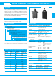
Thermal Overcurrent Circuit Breakers 2-5000/2-5700-...
1
mounting area
max. 2.5
operating area
mounting area
max .098
2-5700-P10
2-5000-P10
A
1432
1432
A
25
25
max. 2.5
11
max .098
operating area
.039
.039
.984
.984
iG1=ø9.6 -0.1
iG2=ø12.2 -0.1
iG1=8.9 -0.1
iG2=11.5 -0.1
blade terminal
DIN 46244-A6.3-0.8
(QC .250)
ø6.5
5
SW 14
iG1=8.8
iG2=11.3
D-shaped threadneck current rating in A for standard
(-DD version without push button marking)
A
1432
iG1=
3
/
8
-27UNS-2A
iG2=M12x1
OFF
ON
1046.5
10.4
19.8
29
tightening torque max. 1 Nm
tightening torque max. 1.5 Nm
14.5
.394
.409
.780
1.14
.551
.256
.571
.886
.650
1.83
16.5
22.5
mounting hole
iG1=.378
-.004
iG2=.480 -.004
iG1=.350 -.004
iG2=. 453 -.004
iG1=.346
iG2=.445
current rating in A
5
1432
18.5
ø4.5
40
50
13
2-5000-P10-A3
0.05...2.5 A
A
1432
ø9.5
5
12.2
18.2
OFF
ON
10.4
44
19.8
31
ø13.5
7
14.5
blade terminal DIN 46244-A6.3-0.8
(QC .250)
.374
.480
1.73
.409
.780
1.22
1.57
1.97
.177
.728 .717
.531
.276
.571
.512
.197
2-5700-P10
2-5000-P10
1432
1432
flat head screw M4x6 ISO1580
tightening torque 1.2 Nm
13
10.4
.409
.512
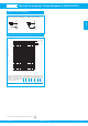
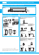
Dimensions Terminal design
Installation drawings
-P10-A3 -K10
0.05...2.5 A
This is a metric design and millimeter dimensions take precedence (
mm
)
inch