
Datasheet

www.e-t-a.com 06/07
1 - 50
Thermal Overcurrent Circuit Breaker 1410-L2/G1
1
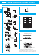
Dimensions Internal connection diagram
1410-L210-L2F1-S02
11
15.7
13
SW14
8.8
.618
.512
.346
.433
2.8
10.15
28
ø7
11
3/8-27UNS-2A
1.2
7.6
7
0.7
11.3
8
32 1
.276
.276
.433
0.8
6.4
.031
.110
.252 .400
.299
.028
.047
.315
.445
blade terminal
DIN 46244-A2.8-0.8
(QC .110)
3
9
.118
.354
ø9.6
- 0.1
8.9
- 0.1
mounting hole
.350
- .004
.378
- .004
~20°
1.10
1410-G111-P2F1-S01
.551
tightening torque max. 0.8 Nm
30
1.18
.299
33
0.8
1
1.2
1.4
0.8
9.6
6.4
10.15
7.6
9
mounting holes
3.5
6.4
±0.2
10.15
7.6
±0.1
+0.1
- 0.2
3.3
32 1
32 1
28
1.10
1.30
.055
.031
.378
.047
.130
.031
.039
.252
.400
.299
.354
.138
7.5
.295
±.004
.252
±.008
.400
+.004
- .008
1410-G114-P3F1-B04-...
1410-G118-L2F1-B04-...
ø11
14.7
0.7
11.3
1.2
3.3
1
28
0.8
9
3
ø15.7
11
13
2
28
8.9
14.2
3/8-27UNS-2A
7
0.7
1.2
12.5
blade terminals
DIN 46244-A4.8-0.5
13
ø15,7
11
8.8
mounting hole
ø9.6
+0
-0.1
ø8.9
+0
-0.1
.559
.028
.276
.492
.047
1.10
.350
3
9
I x 45°
ø4.6
3.5
ø4.6
ø.181
.138
.118
.354
ø.350
+0
-.004
ø.378
+0
-.004
ø.618
.433
.346
.512
ø.433
.579
.118
.354
.445
.028
.047
.130
.020
.039
1.10
ø.618
.512
.433
1
32
12 468102040
… times rated current
Trip time in seconds
10000
1000
100
10
1
0.1
0.01
Typical time/current characteristics at +23°C/+73.4°F
mounting area
operating area
wall
1410-L2..
1410-G...
Installation behind a cover which can only
be removed by means of a tool
Installation drawings
This is a metric design and millimeter dimensions take precedence (
mm
)
inch
All dimensions without tolerances are for reference only. In the interest of improved design,
performance and cost effectiveness the right to make changes in these specifications
without notice is reserved.Product markings may not be exactly as the ordering codes.
Errors and omissions excepted.