
Data Sheet
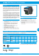
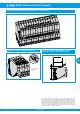

REX12 Electronic Circuit ProtectorREX12 Electronic Circuit Protector
www.e-t-a.de
2
1830
4
REX12D-TE2-100-DC24V-1A-10A
I
N
: 1 A typically 30 mV I
N
: 70 % typically 28 mV
I
N
: 2 A typically 39 mV I
N
: 70 % typically 34 mV
I
N
: 3 A typically 48 mV I
N
: 70 % typically 40 mV
I
N
: 4 A typically 57 mV I
N
: 70 % typically 46 mV
I
N
: 5 A typically 66 mV I
N
: 70 % typically 52 mV
I
N
: 6 A typically 74 mV I
N
: 70 % typically 59 mV
I
N
: 7 A typically 83 mV I
N
: 70 % typically 65 mV
I
N
: 8 A typically 92 mV I
N
: 70 % typically 71 mV
I
N
: 9 A typically 101 mV I
N
: 70 % typically 77 mV
I
N
: 10 A typically 110 mV I
N
: 70 % typically 83 mV
Fail-safe element I
N
: 1 A (CL2) fail-safe I
N
: 1 A
integral I
N
: 2 A (CL2) fail-safe I
N
: 2 A
blade fuse I
N
: 3 A fail-safe I
N
: 3.15 A
adjusted to I
N
: 3A-CL2 fail-safe I
N
: 4 A
related current rating I
N
I
N
: 4 A fail-safe I
N
: 4 A
I
N
: 4 A-CL2 fail-safe I
N
: 4 A
I
N
: 6 A fail-safe I
N
: 6.3 A
I
N
: 8 A fail-safe I
N
: 8 A
I
N
: 10 A fail-safe I
N
: 10 A
I
N
: 1 A/1 A (CL2) fail-safe I
N
: 1 A/1 A
I
N
: 2 A/2 A (CL2) fail-safe I
N
: 2 A/2 A
I
N
: 3 A/3 A fail-safe I
N
: 3.15A/3.15A
I
N
: 3 A/3 A-CL2 fail-safe I
N
: 4 A/4 A
I
N
: 4 A/4 A fail-safe I
N
: 4 A/4 A
I
N
: 4 A/4 A-CL2 fail-safe I
N
: 4 A/4 A
I
N
: 6 A/6 A fail-safe I
N
: 6.3 A/6.3 A
I
N
: 1 A-10 A fail-safe I
N
: 16 A
Operating voltage OFF at typically U
B
< 16.0 V
monitoring re. ON at typically U
B
> 19.0 V
undervoltage hysteresis typically 2 V
with automatic OFF and ON switching
ON delay
- with power ON channel 1: typically 100 ms (REX12-TAx)
channel 2: typically 200 ms (REX12-TAx)
channel 1: typically 1,500 ms (REX12D-TE2)
channel 2: typically 1,600 ms (REX12D-TE2)
- when switching on with channel 1: typically 5 ms
ON /OFF switch or channel 2: typically 100 ms
- after undervoltage channel 1: typically 5 ms
channel 2: typically 5 ms
Disconnection of load circuit - manually on the device with the
ON/OFF momentary switch
- after an overload / short circuit discon-
nection with storage (no automatic reset)
- temporarily at undervoltage
- at no operating voltage
Switch-on of load circuit
- momentary switch ON/OFF device can only be switched on when
operating voltage is applied
- applying The device starts up with the condition
operating voltage last stored.
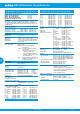
Technical data (T
amb
= +23 °C, U
B
= DC 24 V)
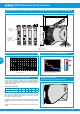
REX12-Txx-xxx circuit protectors
REX12-TA1-107-DC24V-xA 1-channel
REX12-TB1-107-DC24V-xA 1-channel
REX12-TA2-107-DC24V-xA/xA 2-channel
REX12D-TE2-100-DC24V-xA-xA 2-channel
The REX12-TAx is operated in the standard mode with EM12-T. The
REX12D-TE2 can be operated both with EM12D-T or EM12-T. The
operating mode EM12D-T (COM mode) or EM12-T (standard) is
recognised automatically. The following data exclusively refer to the
standard mode.
Operating voltage U
B
DC 24 V (18...30 V)
Closed-circuit current I
0
REX12-Tx1 1-channel in ON condition: typically 5 mA
REX12-TA2 2-channel in ON condition: typically 8 mA
REX12D-TE2 1A-10A 2-channel in ON condition: typically 12 mA
Reverse polarity protection Yes
Power failure
buffering time up to 10 ms
Rated current I
N
ratings:
REX12-Tx1 1 A, 2 A, 3 A, 4 A, 6 A, 8 A, 10 A
REX12-TA2 1 A/1 A, 2 A/2 A, 3 A/3 A, 4 A/4 A, 6 A/6 A
REX12D-TE2 1 A – 10 A Condition upon delivery max.
current rating
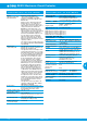
Visual status indication
green: Load circuit connected
by means of LED green/orange
blinking: load current warning limit
reached 90 %
orange: overload or short circuit until
disconnection
red: - after disconnection due to
overload or short circuit
- after undervoltage release of
operating voltage in ON condi-
tion with autoreset
OFF: Device switched off by means of
ON/OFF momentary switch or
no operating voltage
Load circuit
Load output power MOSFET switching output
(plus switching)
Load current warning limit typically 0.9 x I
N
(I
WLimit
)
hysteresis typically 5 %
Overload current typically I
ÜL
: I
N
x 1.05 t
ÜL
: 3s
disconnection (I
ÜL
) typically I
ÜL
: I
N
x 1.35 t
ÜL
: 0,5s
with trip times (t
ÜL
) typically I
ÜL
: I
N
x 2.00 t
ÜL
: 0.1s
typically I
ÜL
: I
N
x 2.50 t
ÜL
: 0.012 s
short circuit typically at short circuit (I
SC
) t
SC
: 0.002 s
2)
trip time (t
SC
) see time/current characteristic
Influence of ambient see temperature factor table
temperature on
overload disconnection
and load current warning limit
Continuous Current IC typically 0.8 x I
N
(Fail Safe Element is protected by
REX12)
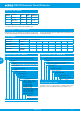
Voltage drop in load circuit at I
N
and at I
N
70 % for REX12-Txx
between LINE+ and LOAD+
I
N
: 1 A (CL2) typically 180 mV I
N
: 70 % typically 125 mV
I
N
: 2 A (CL2) typically 110 mV I
N
: 70 % typically 80 mV
I
N
: 3 A typically 120 mV I
N
: 70 % typically 85 mV
I
N
: 3 A-CL2 typically 130 mV I
N
: 70 % typically 90 mV
I
N
: 4 A typically 115 mV I
N
: 70 % typically 80 mV
I
N
: 4 A-CL2 typically 180 mV I
N
: 70 % typically 120 mV
I
N
: 6 A typically 170 mV I
N
: 70 % typically 110 mV
I
N
: 8 A typically 160 mV I
N
: 70 % typically 105 mV
I
N
: 10 A typically 180 mV I
N
: 70 % typically120 mV
2) depending on power source
Technical data (T
amb
= +23 °C, U
B
= DC 24 V)