000 Brown Rd. Auburn Hills, MI 48326 248.754.1900 jrautomation.
1000 Brown Rd. Auburn Hills, MI 48326 248.754.1900 jrautomation.com REVISIONS Revision Prelim Date 12/28/21 Revised By: Mark Compton Description Preliminary CONTENTS Continuous TPM Antenna User Manual .................................................................................................................... 1 REVISIONS ............................................................................................................................................................... 2 CONTENTS ......
1000 Brown Rd. Auburn Hills, MI 48326 248.754.1900 jrautomation.com GENERAL INFORMATION 1. This device complies with part 15 of the FCC Rules. Operation is subject to the following two conditions: (1) This device may not cause harmful interference, and (2) this device must accept any interference received, including interference that may cause undesired operation. 2. Any changes or modifications not expressly approved by the manufacturer could void the user’s authority to operate the equipment. 3.
1000 Brown Rd. Auburn Hills, MI 48326 248.754.1900 jrautomation.com 14. 15. 16. 17. 18. 19. 20. DO NOT alter or by-pass protective interlocks. DO NOT place jumper wires across fuses. DO NOT alter over-current protective devices. GROUND connections allow fault currents to flow directly into the ground instead of following through the body then into the ground. ALL ELECTRICAL APPARATUS MUST BE PROPERLY GROUNDED. Use CAUTION when connecting test equipment probes to test points.
1000 Brown Rd. Auburn Hills, MI 48326 248.754.1900 jrautomation.com TPM STEM OVERVIEW The purpose of this section is to provide an overview of the TPM valve stems. The scope of this manual is to cover the operation of the JR Automation antenna systems that communicate to the stems, not detailed information on the TPM valve stems themselves. But a general overview of how TPM valve stems operate will help the users understand the operation of the antenna equipment.
1000 Brown Rd. Auburn Hills, MI 48326 248.754.1900 jrautomation.com LF TRANSMISSION (125KHz) THIS MODEL ONLY GENERATES A CONTINUOUS LF TRANSMISSION The JR Automation TPM Antenna systems were developed to utilize the LF (Low Frequency) transmission to collect data from the TPM stem. The TPM stem responds with the 125 kHz wakeup signal can be of 2 different types – Continuous and Modulated LF. Each is described below. Continuous LF: A stem requiring a continuous signal or a signal with no change.
1000 Brown Rd. Auburn Hills, MI 48326 248.754.1900 jrautomation.com RECEIVING UHF SIGNALS After the TPM stem receives the wake up signal it will transmit a UHF data package. The stems transmit data in one of two frequency bands 315 MHz and 433 MHz bands depending on the stems design. Typically, 315 MHz is used in the U.S. and 433 MHz is used in export vehicles. The frequency used is governed by the FCC in the United States.
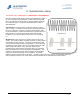
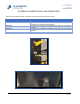
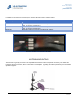
1000 Brown Rd. Auburn Hills, MI 48326 248.754.1900 jrautomation.com EXTERNAL CONNECTIONS & LED INDICATORS The antenna box has 5 external connections. Please see the table & pictures below: Connection Description Power RS485 Antenna 1 Antenna 2 LF Antenna Bulkhead Function Provide 24 VDC power to antenna system Provide RS485 Communication to the antenna from a system controller (provided by System Integrator) Connection for a 315MHz or 433 MHz receiver antenna.
1000 Brown Rd. Auburn Hills, MI 48326 248.754.1900 jrautomation.
00 Brown Rd. Auburn Hills, MI 48326 248.754.1900 jrautomation.