
Instruction manual
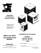


MOTOR PULLEY ADJUSTMENT
Before installing the motor pulley, loosen the set screw on the back side of the pulley and
turn the outside jaw of the pulley until it is fully closed. Position the set screw over the
closest flat spot in the thread and then open the outside jaw of the pulley 4 or 5 turns.
Position the set screw over the closest flat spot in the thread and retighten the set screw.
Place the pulley on the motor shaft and tighten the front set screw. See figure 2. The
CD21 coolers are equipped with double groove pulleys.
OVERFLOW PIPE INSTALLATION
Place the rubber washer onto the drain bushing. Slide the bushing through the drain
opening, in the cooler bottom, from the top side. Screw the nut onto the bushing from
under the cooler.
CAUTION: DO NOT HOOK THIS COOLER TO A WATER SOFTENER. THIS WILL
VOID THE WARRANTY.
WATER CONNECTION
CD75/85: Mount the float in the splash baffle as shown. CS75/85: Mount the float in
the float bracket. Route the ¼” water line through the corner post as shown. Place the
compression nut and ferrule onto the water line. Slide the water line into the float and
tighten the compression nut. See figure 4. As the figure shows, the water level should
remain ½” below the top of the overflow tube. A screw is provided in the float to adjust
water level; or the float rod may be bent to adjust the level.
11/16 & 21: The float mounts in a hole provided in the corner post (down draft) or front
panel (side draft).
BLEEDOFF
In hard water areas, a bleed off kit may be installed to dispose of small
amounts of mineralized water allowing fresh water to replace it.
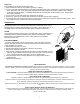
ELECTRICAL POWER
1. The installation of electrical wiring must conform to all local and federal
codes and should be done by a certified electrician.
2. Connecting the motor and/or pump to the wrong voltage will void the
warranty.
Warning: To avoid risk of electrical shock, disconnect the power before
opening or attempting service on this unit.
Notice to Installer: The motor amperage must be set as close as possible to
motor nameplate amps without the pump running.
WIRING DIAGRAMS
A 4” j box has been provided (75/85), in the unit, for
wiring purposes. No other wiring components will be
provided. Single phase: one and two speed.
Three phase; one and two speed. Motor starter to be
equipped with overload relay sized to accommodate
motor full load amps.
Motor starters and overloads are not supplied with units.
PUMP
MOTOR
115V SUPPLY
GREEN
RED
3
PUMP
BLACK
STRIPED
BROWN
SINGLE SPEED
DIAGRAM
RED
3
1
Reservoir
3