
Installation Guide

110524-1
5
AMPERAGE DRAW AND BELT TENSION
CAUTION: No attempt should be made to completely install this unit without the aid of an electrician or
someone familiar with testing amperage draw. Failure to comply with these instructions may void your
warranty.
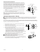
This unit is equipped with an adjustable motor drive pulley for adjusting the blower wheel speed to the proper loading for dierent
duct systems. It is important that the motor drive pulley is adjusted to correct size to ensure maximum air delivery without damage
to the motor. Be sure to follow these instructions carefully.
1. Ensure electrical connection of unit is complete and in accordance with all
safety standards and local requirements.
2. Reinstall inspection panels. Apply power, turn water and pump on and allow
cooler to run for a few minutes to wet pads.
3. Turn o the pump and check amperage and verify it conforms to amperage
listed on the specication label on motor.
• If amperage draw is less than motor rating, disconnect electrical power
and remove louvered sides. Unplug motor inside cooler, this will protect
you from someone turning the unit on while you are working inside. This
should be done for your safety. Adjust pulley to a larger diameter and
readjust belt tension. Plug motor in, install louvered side, and retest amperage
draw. Repeat this process until correct amperage draw is attained.
Note: Increasing motor pulley diameter increases amperage draw. Decreasing
motor pulley diameter decreases amperage draw.
CAUTION: DO NOT operate cooler with larger amperage draw than
specied on motor plate. Motor damage will occur.
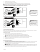
4. Check belt tension after adjusting pulley. A 3 lb. force should deect the belt 3/4
inches. Readjust belt if needed by loosening adjustment screw, rotate motor until
you have the correct belt tension, then re-tighten screw.
SCALE BUILDUP PREVENTION
As water evaporates, minerals that were in the water will remain. Over time this
accumulation of minerals will cause scaling on the pads and in the reservoir. We
recommend the installation of either a bleed-o kit (included in standard 4000RLD4
unit) or a purge pump (installed in contractor 4000CRLD4 unit) to help prevent
scale build up and increase the life of the unit. A purge pump will drain the pan
every few hours of pump operation, to keep fresh water in the unit. A bleed-o kit
will continually bleed o a small portion of water while the pump is running allowing
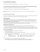
fresh water to continually replace the old stagnate water. Follow the instructions
below for installing the bleed-o kit.
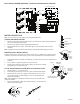
1. Cut the pump hose and insert the barbed ends of the bleeder tee into each
cut end.
2. Insert one end of the bleeder tubing onto the bleeder tee and run the other
end out of the cooler through the overow pipe.
Note: A restrictor clamp is provided which, if desired, may be installed onto the
bleeder tubing to restrict the amount of water being bleed o. The amount of water
to bleed o depends on the quality of the water in your area. Start with 1-2 gal/hr
and increase if needed.
Bleeder Tee
Bleed Tube
Restrictor
Overow Pipe
Pump Hose
BLEED-OFF KIT
Decrease
Amperage
Motor
Motor
Pulley
Blower
Pulley
Belt
3 Lb. Pressure
3/4 Inches
BELT TENSION