
Installation Guide

110524-1
4
WATER CONNECTION
Note: Do not connect the water supply to any soft water applications.
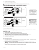
OVERFLOW INSTALLATION
1. Remove nut and place nipple through the hole in the pan with the rubber washer between the
pan and the head of the drain nipple.
2. Screw nut onto nipple and draw up tight against bottom pan.
3. Screw overow pipe into nipple. This overow pipe may be removed to drain pan when
necessary.
Note: A garden hose may be screwed onto the drain nipple to drain water away from the unit.
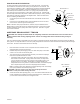
WATER SUPPLY INSTALLATION
A steady water supply is required for the operation of this cooler. A saddle valve or sillcock valve is
required to connect to a local water supply. These can be purchased from a local hardware store.
1. Install saddle valve to an interior cold water pipe, or install a sillcock valve to an exterior faucet
as shown.
2. Run ¼” plastic or copper tubing from the valve to the unit.
3. Install one end of tubing to water valve by placing nut and ferrule on tubing
and tightening the nut until water tight.
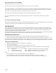
FLOAT VALVE INSTALLATION (Refer to illustration below)
1. Remove items 2, 3, 4, and 5 from oat.
2. Insert oat body through hole in the corner post or oat bracket as shown.
3. Install washer (2) and nut (3). Tighten to keep oat from turning. Place
nut (5) and ferrule (4) on water supply line. Connect to oat tting and
tighten until water tight.
Note: After installation is complete and water is turned on, the oat level will
need to be adjusted.
4. Bend rod to adjust oat. Water level should be about 1 inch below the top
opening of the overow pipe.
Faucet
Water Shut
O Valve
Sillcock With Std.
Hose Connection
Ferrule
Nut
Copper Or
Plastic Line
To Cooler
Rubber Washer
Overow Pipe
Nipple
Reservoir
Nut
Cold
Water
Pipe
Saddle
Valve
1/4” Tubing
Float
Corner
Post
Bracket
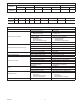
FAN MOTOR
PP
RECEPTACLE
DUMP
BROWN
THERMOSTAT
BLUE
RED
SWITCH LEADS
WHITE
LINK
WHITE
L1
RECEPTACLE
PCom
DRAIN PUMP
PUMP
ORANGE
WHITE/RED
WHITE/BLUE
GREEN
FLo
BLUE
N
RECEPTACLE
DP
ORANGE
FAN
ORANGE
BLACK
WHITE
WHITE
FHi
BLUE
NLink
CIRCULATING PUMP
DCom
BROWN
PWR. SUPPLY
VIOLET
BLACK/RED
=WIRE NUT
BLACK
FCom
120 VAC
GREEN
GREEN
SUPPLY
WHITE
BLACK
POWER
COOLER TERMINAL BOX
GREEN
RED
WHITE
DISCONNECT SWITCH
GROUND
SUPPLIED BY INSTALLER
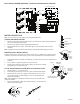
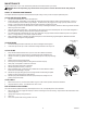
ELECTRICAL WIRING DIAGRAM - CONTRACTOR 4000CRLD4 COOLER
1
2
3
5
6
4