
Installation guide

Network Infrastructure for EtherNet/IP™
7-87
Selecting Components
7.3.1 Address Table Size Limits Control Device Quantity
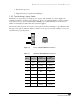
Switches learn what devices are connected to each port by noting the address of each device that transmits
(is the source of) a message. These addresses are stored in a look-up table in the switch’s memory. Each
switch has a finite capacity for stored addresses—usually several thousand. A switch updates its list using
a process termed
aging by periodically (ranging from tenths of seconds to minutes) removing addresses
from which it has not received a message. If it receives a subsequent message from the device, the switch
restores the device address to the table.
If a factory-floor system has thousands of connected devices, and it interconnects other systems that
regularly broadcast messages that may pass through part of the control system, it is possible for a switch
to run out of address table memory. Routers can block undesired broadcasts. Undesired broadcasts can
also be contained through use of VLANs.
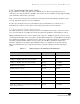
7.3.2 Auto-negotiation vs. Manual Setting of Switched Port Data Rates
The ports on most switches support both 10 Mbps and 100 Mbps—and many, 1 Gbps—data rates and
half- or full-duplex operation. The capability of switches to automatically configure to the data rate (and
half- versus full-duplex operation) of another auto-negotiation device that is connected can be a drawback
in certain cases. When two auto-configuration devices are connected, they will first attempt to connect at
the highest data rate, usually 100 Mbps. This can be undesirable in two cases:
•
High electrical noise environments with twisted-pair cable. Manually setting the
ports to 10 Mbps can provide a higher degree of noise immunity when using twisted-pair
cable.
•
Fiber-optic cable runs. Auto-negotiation is only offered for twisted-pair cabling and
10-Mbps fiber segments. The 100 Mbps data rates for fiber cables must be set manually.
7.3.3 Multicast Messaging Handling Option
EtherNet/IP can use multicast Ethernet frames for real-time communications. A typical switch will
receive multicast (and broadcast) messages, and then rebroadcast them to the remaining switch’s ports.
Layer 2 and Layer 3 switches with IGMP snooping or equivalent functions learn which multicast
messages to send to which ports.
7.3.4 Quality of Service Options
Switches can prioritize traffic based on MAC addresses, IP addresses, switch port numbers, and protocol
identification information. This ability to prioritize and provide a different QoS based on the message
type can help improve real-time performance. It requires the user to enter QoS configuration information
into the Layer 2 or Layer 3 switch.
7.3.5 Security Options
Switches can maintain port-based Access Control Lists (ACL). This capability prevents unauthorized
access into the control network based on the user entering a MAC address or a port-number-based ACL.
This approach is also used to disable unused ports, so they cannot be used for unauthorized network
access.