
Installation guide

Network Infrastructure for EtherNet/IP™
7-85
Selecting Components
7.2.3 When to Use Fiber-Optic Cabling
Fiber should be considered when the required length is greater than 100 meters (328 ft) between two
devices. If an application creates high magnetic and electric fields, fiber should be considered.
Applications such as magnetic galvanizing annealing furnaces and high-power RF cross-linking machines
are ideally suited to the use of fiber-optic cabling.
7.2.4 Types of Optical Fiber
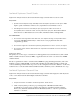
Optical fiber consists of five basic elements: core, cladding, strength members, coating, and outer jacket.
The core, constructed of either glass or plastic, provides the basic means for transmitting the light energy
down the cable. The cladding prevents the light from exiting the core and being absorbed by the cable
itself. The coating protects the core while providing strength. An overall jacket provides final protection
and may consist of other strengthening and protective elements. Strength members provide protection
when pulling the cable and for securing the connector.
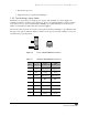
Classification of Optical Fibers
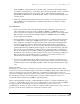
Optical fibers are classified by their diameter in microns. A micron is a millionth of a meter and is
designated by the symbol µm. The core, cladding, and coating frequently are specified using slashes
(/) to separate the values. For example, 50/125/250 means that the core is 50 µm, the cladding is 125
µm, and the coating is 250 µm. Since the cable dimensions all pertain to the concentric diameters of
the various elements, a concise way of specifying the fiber is to list only the core and cladding sizes.
In the above example, this fiber would be classified as 50/125. Core sizes range from as small as 5
µm to as large as 1000 µm.
Depending on the core size, the cable transmits light in either one or two modes: single-mode or multi-
mode. For each fiber-optic link, a pair of fibers is required. Usually several fibers are pulled to provide
spares. The most popular multi-mode fiber-optic cables are 62.5/125 µm and 50/125 µm. A single-mode
fiber-optic cable will have an inner core diameter of 10 µm or less.
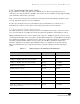
7.2.5 Bend Radius / Pull Force of Fiber
Bend radius is defined as the radius of curvature that a fiber-optic cable can bend without causing any
adverse effects. Each manufacturer will have different ratings for each of its products. It’s important to
refer to the fiber-optic cable manufacturer’s data sheet for specific pulling force and bend radius
recommendations when installing fiber-optic cable.
In the absence of this data, the pulling force should be limited to no more than 222 N (50 lbs) and the
bend radius under load generally should be limited to 20 times the outside diameter of the cable and to 10
times the outside diameter under static conditions. For more information on fiber-optic bend radius, see
the BICSI (a telecommunications association) Telecommunications Distribution Methods Manual.
23
23
BICSI, Inc., Telecommunications Distribution Methods Manual, 11
th
Edition, BICSI, Inc., Tampa: 2006. www.bicsi.org