
Installation guide

Network Infrastructure for EtherNet/IP™
7-82
Selecting Components
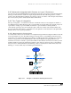
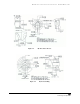
7.1.2 M12 “D”-Coded Connector for EtherNet/IP
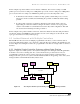
The EtherNet/IP™ Specification also allows the use of the four-pin, “D”-coded M12 connector for IP65-
and IP67-rated environments. This device is shown on the left in Figure 7-3 and is the pin-and-socket
style connector for EtherNet/IP. It will be familiar to many engineers from its standard version, which is
in widespread use in industrial applications, such as with sensors and actuators. The connectors are not
quite the same, however, and for good reason. The “D-coding” keying is different from the standard M12
connector to prevent accidental connection of other devices that may have high enough voltages to
damage Ethernet circuits. The connector provides for two-pair shielded cables, and a variety of cables can
be used to withstand most industrial conditions.
Figure 7-3 Comparison of “D”-Coded and Standard M12 Connectors.
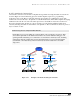
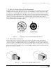
7.1.3 Fiber-Optic Connectors
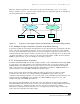
For fiber optics, there are three types of approved connectors: the quarter-turn LC, ST and the SC
connectors. The ST (for straight-through) is shown on the left in Figure 7-4, and the SC (for standard
connector) is shown on the right. The LC connector is a smaller version of the SC. A pair of fibers are
used for each link to support separate receive and transmit paths. Therefore, like twisted-pair connections,
receivers must be tied to transmitters. Ports on both the DTE and DCE are marked as TX (transmit) and
RX (receive) to guide connections.
Figure 7-4 ST (left) and SC (right) Fiber-Optic Connectors.
1
2
3
4
M12 (D-coding)
Standard M12