
Installation guide

Network Infrastructure for EtherNet/IP™
6-74
Infrastructure Application Scenarios
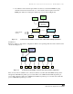
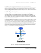
In this example, if producer traffic is unicast instead of multicast, then switch 4 will process 600
packets per second,
switch 3 will process 1200 packets per second, switch 2 will process 1800 packets
per second, and
switch 1 will process 2400 unicast packets per second. It is important to note:
• In this unicast environment, no matter how many packets a switch will process, no nodes
will receive extraneous traffic, thus eliminating the potential of a multicast traffic loading
problem.
• In a daisy-chain connection of switches in this unicast environment, switch 1 has very
high loading. To reduce the additive loading from switch to switch, a star topology with
switch 1 in the middle is recommended instead of the daisy chain configuration. This will
also decrease the individual port loading on switch 1.
In this example, if the produced traffic is
multicast, and both workstation and remote I/O performance
are affected, switches with IGMP snooping should be used. To even loading across the network, a star
topology is used instead of a daisy-chain topology.
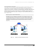
6.3 Isolated Network with Multiple Controllers
EtherNet/IP networks can consist of multiple programmable controllers (or other controllers such as
motion) and still remain isolated—not connected to other networks. One example is the VLAN approach
shown in Figure 6-8 and Figure 6-9 where two programmable controllers use a single switch to connect to
their I/O.
6.3.1 Multiple Single-Controller Systems without Data Sharing
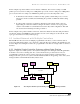
Figure 6-8 depicts two small, separate control systems sharing the same managed switch. Programmable
Controllers 1 and 2 are not sharing data. Also, each of the I/O devices produces data for only one
programmable controller. In other words, this represents two single-consumer systems that share a
managed switch. To prevent one system’s unwanted multicast traffic from appearing on the other system,
managed switches with VLAN functionality must be used.
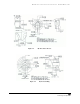
Figure 6-8 Two Single-Controller Systems Sharing a VLAN-enabled Managed Switch.
12-port Switch
I/O
11
I/O
12
I/O
13
Programmable
Controller 1
Workstation 1
I/O
21
I/O
22
Programmable
Controller 2
Workstation
2