
Installation guide

Network Infrastructure for EtherNet/IP™
Deploying the Network
5-63
office networks, where IP multicast traffic is generated sporadically and with much lower packet rates. A
growing exception to this traffic profile may be in the area of multimedia audio and video conferencing
applications.
EtherNet/IP Specification Tip
In accordance with The EtherNet/IP™ Specification, a message producer can send data
encapsulated in either an IP unicast or IP multicast packet.
5.2.2 IP Addressing in EtherNet/IP Networks
In some EtherNet/IP products, transfer of CIP-implicit messages is performed using connectionless
transport layer protocol, UDP, and multicast services of underlying protocols, namely IP and Ethernet.
Only
“heartbeats” are transferred as UDP unicast packets. Therefore, the first half of a transaction
constituting implicit message transfer from a producer to a consumer is a UDP/IP multicast packet
transmitted by the producer, and the second half is a UDP/IP unicast packet transmitted by the consumer.
In the case of multiple consumers, each consumer transmits a “heartbeat” packet to the producer.
If an EtherNet/IP bridge or adapter has a maximum packet rate of 5000 packets per second, it means that
a maximum of 2500 packets per second can be transmitted by this device, and a maximum of 2500
packets per second can be received by it. Therefore, the maximum UDP/IP multicast packet rate of this
device is 2500 packets per second.
It is important to remember that the destination address of an IP multicast packet is always selected from
a specific range, called
Class D and, in the case of some EtherNet/IP products, from a specific sub-class
within it. Therefore, as an example, these products generate IP multicast addresses from 239.192.xxx.xxx
to 239.193.xxx.xxx.
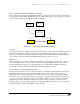
5.2.2.1 IP Addressing Example
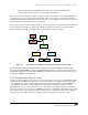
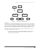
Consider an EtherNet/IP network consisting of a programmable controller system acting as a consumer, a
remote I/O rail acting as a producer, and a managed switch. Assume that the consumer has been
configured with the IP address 10.88.80.100, the producer has been configured with the IP address
10.88.80.110, and the switch has been configured with the IP address 10.88.80.120. The CIP connection
has been configured with a 10-millisecond (ms)
Requested Packet Interval (RPI). See 6.1.1 Multicast
Traffic Management within a Control System for more information.
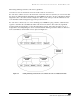
During the CIP connection establishment process, the consumer sends a CIP Forward_Open Request
packet to the producer. This is a TCP/IP unicast packet with IP Destination Address 10.88.80.110 and IP
Source Address 10.88.80.100. In response, the producer sends a CIP Forward_Open Response packet
back to the consumer, which contains an IP multicast address in its Data field that the producer will use to
send data to the consumer on this CIP connection. The Forward_Open Response packet is also a TCP/IP
unicast packet but with IP Destination Address 10.88.80.100 and IP Source Address 10.88.80.110.
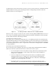
Assume that the IP multicast address generated by the producer is 239.192.1.1. As soon as a CIP
connection has been established, the producer begins multicasting a UDP/IP packet containing the status
of its inputs every 10 ms. The IP Destination Address of this packet is 239.192.1.1, and the IP Source
Address is 10.88.80.110. The consumer responds by sending a “heartbeat” packet, which in this example
contains the output status update. This packet is a UDP/IP unicast packet with the IP Destination Address