
Installation guide


Network Infrastructure for EtherNet/IP™
Deploying the Network
5-59
cabinets to protect them from shop-floor environments. For critical applications, the use of more durable
sealed connectors will stand up to the rigors of plant-floor environments.
Testing is easily done with commercially available hand-held network testers. Special adapters may be
necessary for sealed connectors. Testing output includes conformance to all electrical requirements
including, but not limited to, attenuation, impedance, return loss, cross-talk, and cable segment length
measurements.
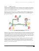
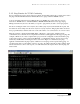
5.1.1 Link and Other Diagnostic LEDs
When deploying EtherNet/IP networks or diagnosing existing networks, engineers can take advantage of
a few low-level, built-in diagnostic “tools” found on switches, routers, hubs, and network adapter cards
on computers or industrial equipment. One of these tools is the built-in link/activity LED.
The
link LED indicates a connection between two EtherNet/IP devices. These can be two switches, a
switch and a computer, a switch and a PLC, etc. How the device knows there is a proper link is that each
EtherNet/IP device, when not transmitting data, will transmit a link signal on all of its EtherNet/IP ports.
When either device receives this link signal, it will then turn on the link LED associated with that port.
Therefore, if the wiring is correct between two EtherNet/IP device ports, the appropriate link LEDs will
be enabled on each of the devices at both ends of the cable.
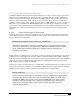
There may also be
speed LEDs and type of duplex connection LEDs that indicate the speed (10 Mbps,
100 Mbps, etc.) and the type of duplex connection (half- or full-duplex) between the two devices. Some
devices may use a multicolor LED to indicate speed. For example, amber may indicate 10 Mbps with
green for 100 Mbps. Both sides of the connection must use the same speed and the same duplex settings
for proper communications. Most equipment will automatically negotiate for the fastest speed and for
full-duplex operation. If both devices connected to a cable show a 10-Mbps and half-duplex setting when
they are rated for 100-Mbps and full-duplex operation, this may be an indication of a defective cable. It is
also possible that there may be a physical problem with the adapter’s circuit at either end, or a
configuration switch may be set for manual operation, locking in the speed or mode of operation.
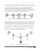
Many switches and EtherNet/IP devices also provide an
activity LED to indicate data transmission
activity. Sometimes the link LED flashes to indicate either receive or transmit activity. The
manufacturer’s manual should be reviewed for specific details.
The link LED will indicate a working connection between two EtherNet/IP devices. The activity LEDs
will show that one of the two devices is transmitting data. The speed and duplex LEDs can provide
further diagnostic information. Sometimes a single LED will be used to show multiple functions. In some
cases a router or switch may even have separate LEDs to show transmit and receive (or upload and
download) functions. In many cases, there is not consistency from device to device. It’s best to check the
manual to confirm what the various LEDs indicate.
In rare cases, link LEDs can show a proper connection between two devices even though the cable may
be constructed improperly. Communication may still occur over an improperly wired cable, but it may be
intermittent or contain errors. A
cable tester tool should be used to check all cables to evaluate fully the
cable wiring. Fiber-optic cables can have a similar problem, especially if they have to be terminated in the
field under poor lighting or temperature conditions.