
Installation guide


Network Infrastructure for EtherNet/IP™
Designing the Infrastructure
4-55
Layer 3 switching operates at the network layer. It examines packet information and forwards packets
based on their network-layer destination addresses. Layer 3 switching also supports router functionality.
As routers operate at Layer 3 of the OSI Model, they can adhere to and formulate a hierarchical
addressing structure. Therefore, a routed network can tie a logical addressing structure to a physical
infrastructure, for example, through TCP/IP subnet networks for each segment. Traffic flow in a
switched (flat) network is, therefore, inherently different from traffic flow in a routed (hierarchical)
network
. Hierarchical networks offer more flexible traffic flow than flat networks because they can use
the network hierarchy to determine optimal paths and contain broadcast domains.
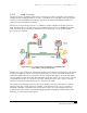
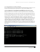
Figure 4-14 Flow of Inter-subnet Traffic with Layer 2 Switches and Routers.
As shown in Figure 4-14, for the PC client to communicate with Server 1, which is on another subnet, it
must traverse through Switch 1 (a Layer 2 switch), then through the router (a Layer 3 switch) and, finally,
through Switch 2 (a Layer 2 switch). There is the potential for a tremendous bottleneck, which can
threaten network performance, because the inter-subnet traffic must pass from one network to another.
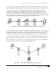
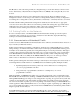
To relieve this bottleneck, network designers can add Layer 3 capabilities throughout the network. By
implementing Layer 3 switching on edge devices, they can alleviate the burden on centralized routers.
Figure 4-15 illustrates how deploying Layer 3 switching throughout the network allows the PC client to
communicate directly with Server 1 without passing through the router.
Figure 4-15 Flow of Inter-subnet Traffic with Layer 3 Switches.