
Installation guide


Network Infrastructure for EtherNet/IP™
Designing the Infrastructure
4-54
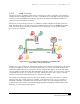
4.11 Multilayer Ethernet Switches
A multilayer Ethernet switch performs the traditional function of a Layer 2 device but also can perform
functions based on information from other layers of the networking stack. For example, a multilayer
switch can inspect the IP information encapsulated in an Ethernet frame and perform routing decisions
based on it (Layer 3 switching), assign a given priority to the frame (QoS), and deny or permit access
(security). A Layer 4-aware switch could do the same based on UDP or TCP ports (source or destination).
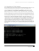
This can be a very useful feature in EtherNet/IP networks as a switch can be configured to give high
priority to the Common Industrial Protocol (CIP) traffic based on the UDP port destination/source in the
datagram. It also could prevent unauthorized users from accessing the network by checking their IP
addresses.
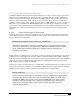
4.11.1 Layer 2 and Layer 3 Switching
Switching is the process of taking an incoming frame from one interface and delivering it out through
another interface. Routers use Layer 3 switching to route a packet, and switches (Layer 2 switches) use
Layer 2 switching to forward frames.
The Difference between Layer 2 and Layer 3 Switching
The difference between Layer 2 and Layer 3 switching is the type of information inside the frame
that is used to determine the correct output interface. With Layer 2 switching, frames are switched
based on MAC address information. With Layer 3 switching, frames are switched based on
network-layer information.
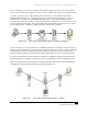
Traditional Layer 2 switching does not look inside a packet for network-layer information as does Layer 3
switching. Layer 2 switching is performed by looking at a destination MAC address within a frame. It
looks at the frame’s destination address and sends it to the appropriate interface if it knows the destination
address location. Layer 2 switching builds and maintains a switching table that keeps track of which
MAC addresses belong to each port or interface.
If the Layer 2 switch does not know where to send the frame, it transmits the frame out on all its ports and
is said to
flood the ports to learn the correct destination. When the frame’s reply is returned, the switch
learns the location of the new address and adds the information to the switching table.
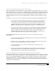
Layer 2 Addresses
Layer 2 addresses are determined by the manufacturer of the data communications equipment. They
are unique addresses that are derived in two parts: the manufacturing (MFG) code and the unique
identifier. The MFG code is assigned to each vendor by the IEEE. The vendor assigns a unique
identifier to each board it produces. Layer 2 addresses are fixed with a device, whereas Layer 3
addresses can be changed. In addition, Layer 2 addresses assume a flat address space with
universally unique addresses.