
Installation guide

Network Infrastructure for EtherNet/IP™
Designing the Infrastructure
4-51
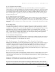
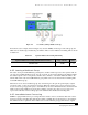
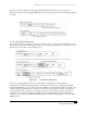
Figure 4-11 depicts an Ethernet frame tagged with an 802.1Q field, which consists of a two-byte
Ethertype and a two-byte 802.1Q Tag. Within the two-byte tag are the user priority bits (known as 802.1p
CoS bits).
Figure 4-11 Details of Ethernet Frames and IP Packet.
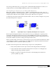
4.9.3 Priority Mechanisms
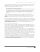
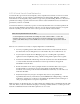
For any QoS services to be applied to data, there must be a way to “tag” or prioritize an IP packet or an
Ethernet frame. The Layer 2 802.1p Class of Service (CoS) and Layer 3 IP Type of Service (ToS) are the
fields used to achieve this as shown in Figure 4-12.
Figure 4-12 Prioritization of IP Packets.
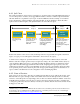
There are several parameters to take into account when considering Layer 2 through Layer 4
classification. A switch can implement Layer 2 classification (as shown in the “Encapsulated Packet”
diagram within Figure 4-12) by looking at the Layer 2 Header and classifying the frame accordingly. An
advanced managed switch may also view any CoS value that comes tagged on a frame coming into the
switch and will use this information to determine the priority that it should be assigned, then take the
appropriate actions. Feature rich switches will also process the packets based on Layer 3 IP address
information as well as Layer 4 (TCP and UDP) information, and the Differentiated Services Code Point
(DSCP) value.